27
Installation Section 2-1
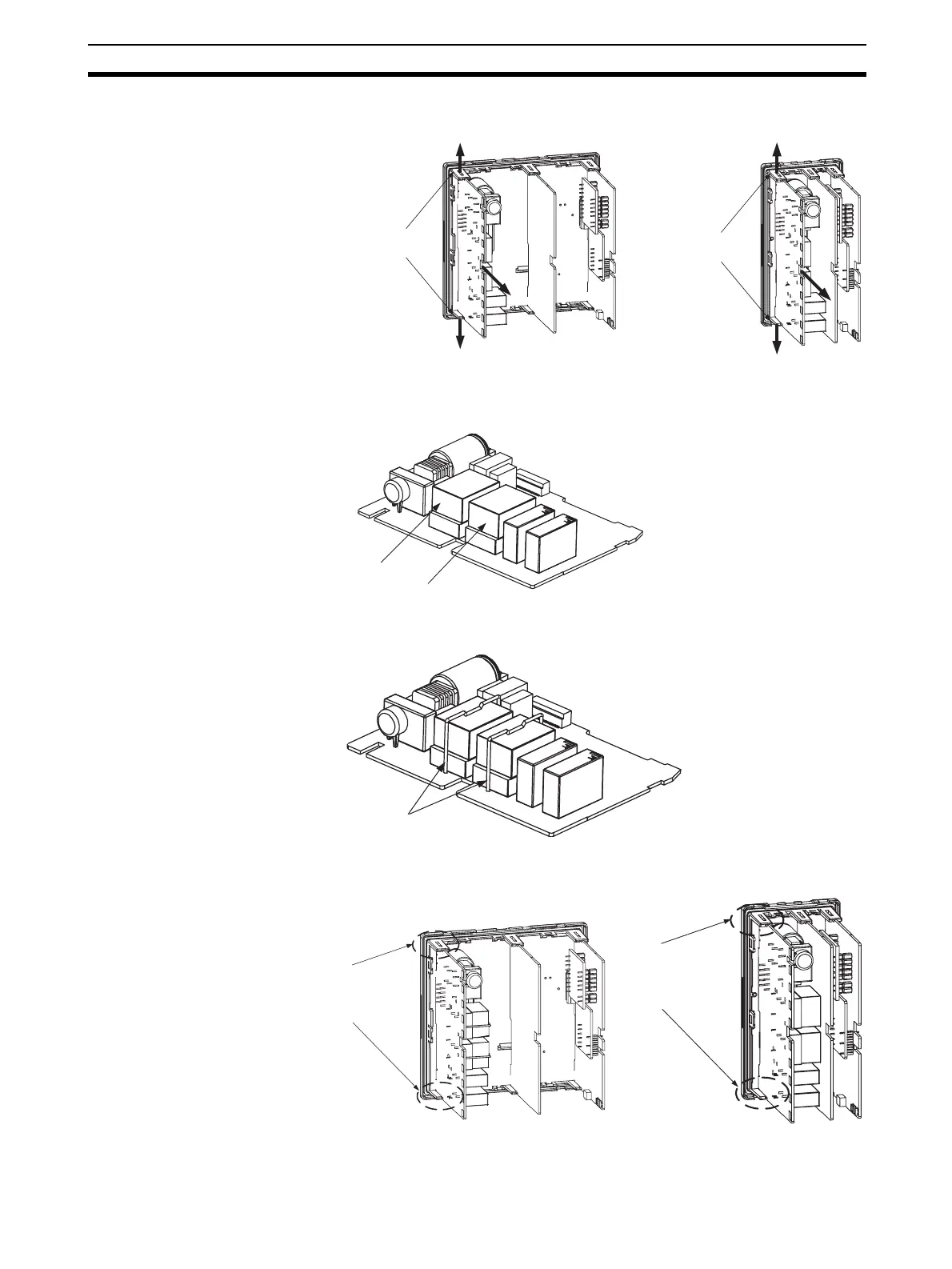
1,2,3... 1. While lifting the hooks securing the PCB on the front panel, remove the
PCB to which the sockets are attached.
2. Set the Output Unit for control output 1 in the OUT1 socket. Set the Output
Unit for control output 2 in the OUT2 socket.
3. For the E5AN-H, use the enclosed clamps to secure the Output Units. Do
not use clamps for the E5EN-H.
4. Set the PCB back in its original location, and make sure that the hooks se-
curing the PCB are firmly in place.
E5AN-H
Hooks securing PCB
E5EN-H
Hooks securing PCB
OUT1
OUT2
Clamps
E5AN-H
Confirm that the hooks
securing the PCB are
firmly in place on the top
and bottom.
E5EN-H
Confirm that the hooks
securing the PCB are
firmly in place on the top
and bottom.