33
Wiring Terminals Section 2-2
• Take countermeasures such as installing a surge absorber. As an addi-
tional safety measure, provide error detection in the control loop. (Use the
Loop Burnout Alarm (LBA) and HS alarm that are provided for the E5@N-
H.)
Select a surge absorber that satisfies the following conditions.
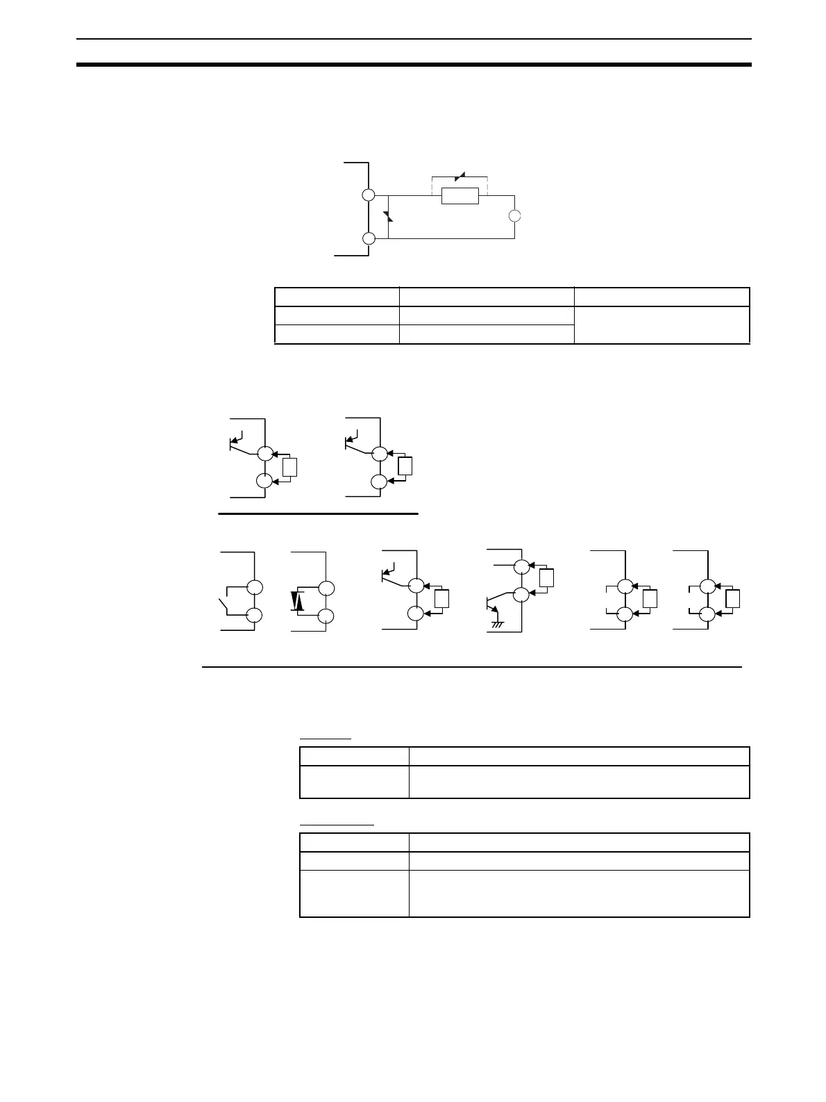
Control Output 2 • Outputs are sent from terminals 11, 12, 14, and 15 with the E5CN-H, and
from pins 5 and 6 with the E5AN/EN-H. The following diagrams show the
available outputs and their internal equalizing circuits.
• The following table shows the specifications for each output type.
E5CN-H
E5AN/EN-H
Note The SSR output (control output 1 or control output 2) ratings are as
follows:
• Rated load voltage: 75 to 250 VAC
• Rated load current: 1 A (resistance load)
Use the load current within the derating curve.
Voltage used Varistor voltage Surge resistance
100 to 120 VAC 240 to 270 V 1,000 A min.
200 to 240 VAC 440 to 470 V
4
3
SSR output
Varistor
Load
Varistor
~
E5AN/EN-H
Relay
GND
Voltage (for driving SSR)
E5CN-H
or
+
v
L
+
−
+
v
L
+
−
+
−
L
V
+
−
L
mA
+
v
L
+
−
+
v
L
+
−
Voltage (for driving SSR)
GND
GND
GND
SSR
E53-Q4 (PNP)
E53-QN (PNP)
E53-Q3 (NPN)
E53-V34N
E53-V35N
E53-C3N
E53-C3DN
14
15
11
12
5
6
5
6
5
6
5
6
5
6
5
6
Output type Specifications
Voltage (for driv-
ing SSR)
PNP type, 12 VDC ±15%, 21 mA (with short-circuit protec-
tion)
Output type Specifications
SSR 75 to 250 VAC 1 A (See note.)
Relay (Position-
proportional mod-
els)
250 VAC 1 A (including inrush current)