43
Using Infrared Communications Section 2-4
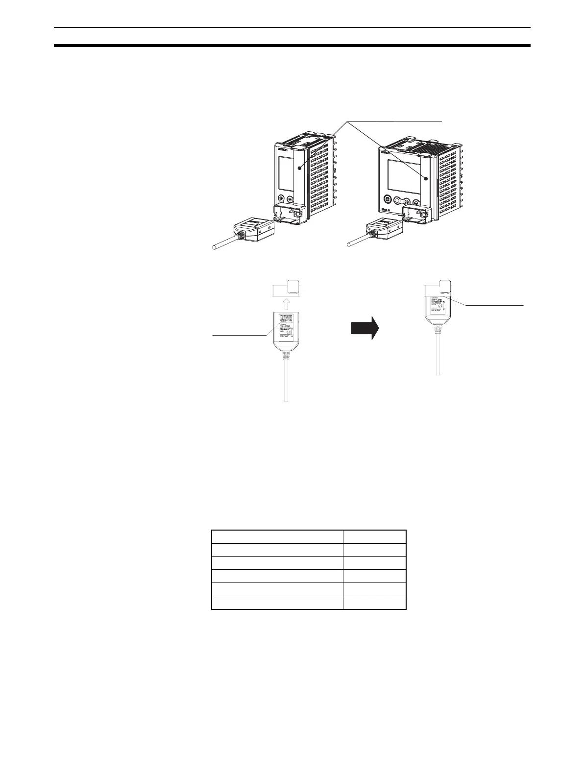
4. Connecting the USB-Infrared Conversion Cable to the Digital Controller
Mount the enclosed adapter to the Digital Controller. Hold the USB-Infra-
red Conversion Cable with the label side facing up, and insert the Cable
into the adapter to the line specified on the label.
5. Setting the Setup Tool Communications Conditions
Set the communications port (COM port) number to be used for the CX-
Thermo Setup Tool to the COM port number assigned to the USB-Infrared
Conversion Cable.
Refer to the E58-CIFIR USB-Infrared Conversion Cable Instruction Sheet
and Setup Manual for details on checking the COM port assigned to the
USB-Infrared Conversion Cable. The communications conditions for infra-
red COM ports are fixed as shown in the table below. Set the communica-
tions conditions for the CX-Thermo Setup Tool according to the following
table.
6. Checking the Settings
After completing all data transfers, be sure that the data is correct. Finally,
remove the USB-Infrared Conversion Cable and mounting adapter from
the Digital Controller and set the Infrared Communications Use parameter
to OFF. Operation can now be started.
Turn ON the Infrared Communications Use parameter only when connect-
ed to the Setting Tool through infrared communications. Leave it set to OFF
during normal operation.
Parameter Set value
Communications Unit No. 01
Communications baud rate 38.4 (kbps)
Communications data length 7 (bits)
Communications stop bits 2 (bits)
Communications parity Even
Mounting adapters
E5EN-H Series
E5AN-H Series
Line on label
Insert up to the line