61
Determining PID Constants (AT, ST, Manual Setup) Section 3-8
AT Calculated Gain
The AT Calculated Gain parameter sets the gain for when PID values are cal-
culated using AT. When emphasizing response, decrease the set value. When
emphasizing stability, increase the set value.
AT Hysteresis
The AT Hysteresis parameter sets the hysteresis when switching ON and OFF
for the limit cycle operation during auto-tuning.
Limit Cycle MV Amplitude
The Limit Cycle MV Amplitude parameter sets the MV amplitude for limit cycle
operation during auto-tuning.
Note Disabled for 100% AT.
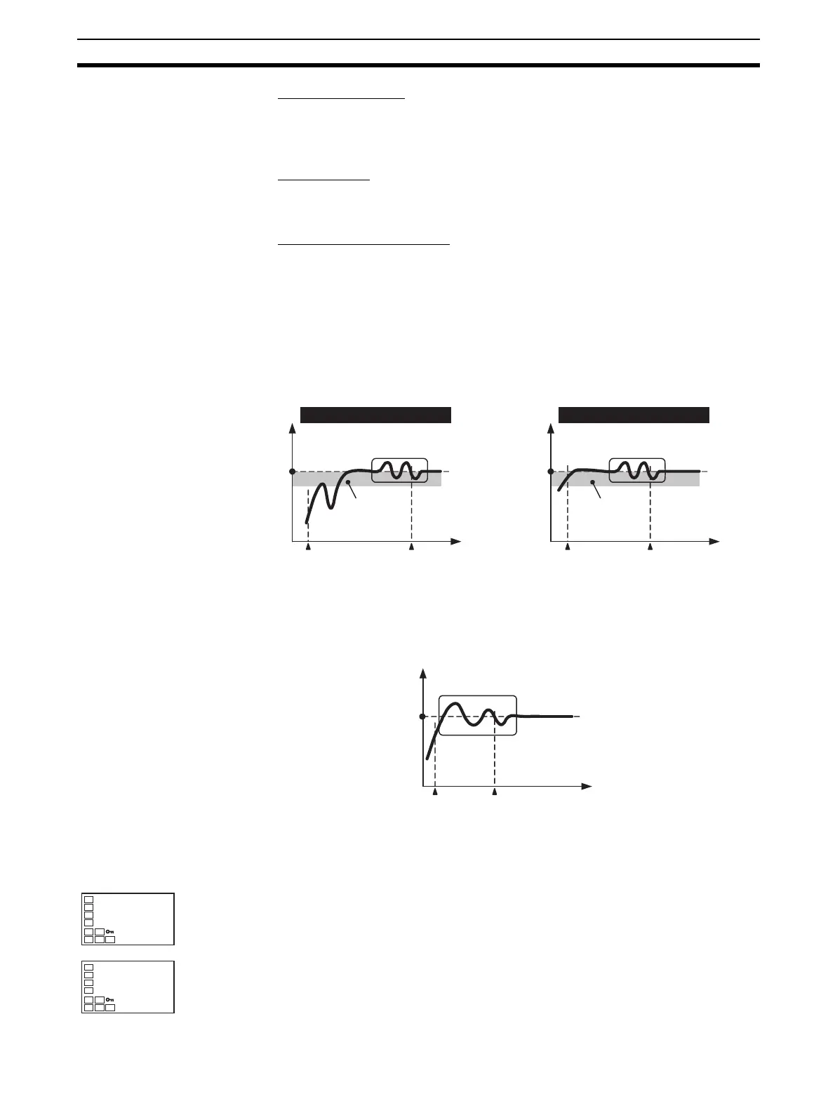
■ 40% AT
The width of MV variation in the limit cycle can be changed in the Limit Cycle
MV Amplitude parameter, but the AT execution time may be longer than for
100% AT. The limit cycle timing varies according to whether the deviation (DV)
at the start of auto-tuning execution is less than 10% FS.
■ 100% AT
Operation will be as shown in the following diagram, regardless of the devia-
tion (DV) at the start of AT execution. To shorten the AT execution time, select
100% AT.
Note The Limit Cycle MV Amplitude parameter is disabled.
Operating Procedure This procedure executes 100%AT.
SP
PV
AT started
AT ended
Time
Limit Cycle MV
Amplitude 40%
Deviation ≥ 10% FS
Deviation:
10% FS
Time
Deviation < 10% FS
SP
PV
AT started AT ended
Limit Cycle MV
Amplitude 40%
Deviation:
10% FS
SP
PV
AT started AT ended
Time
Limit Cycle MV
Amplitude 100%
Adjustment Level
1. Press the O Key to move from the operation level to the adjustment level.
Press the M Key to select the AT Execute/Cancel parameter.
2. Press the U Key to select at-2. The No. 1 display for AT Execute/Cancel
will flash during AT execution.
at
off
AT Execute/
Cancel
at
at-2
 Loading...


