Controlling Operation and Outputting Data with EtherNet/IP Communications
104
FQ2-S/CH User’s Manual
for Communications Settings
If measurements are executed in parallel, the EtherNet/IP BUSY signal will also turn ON.
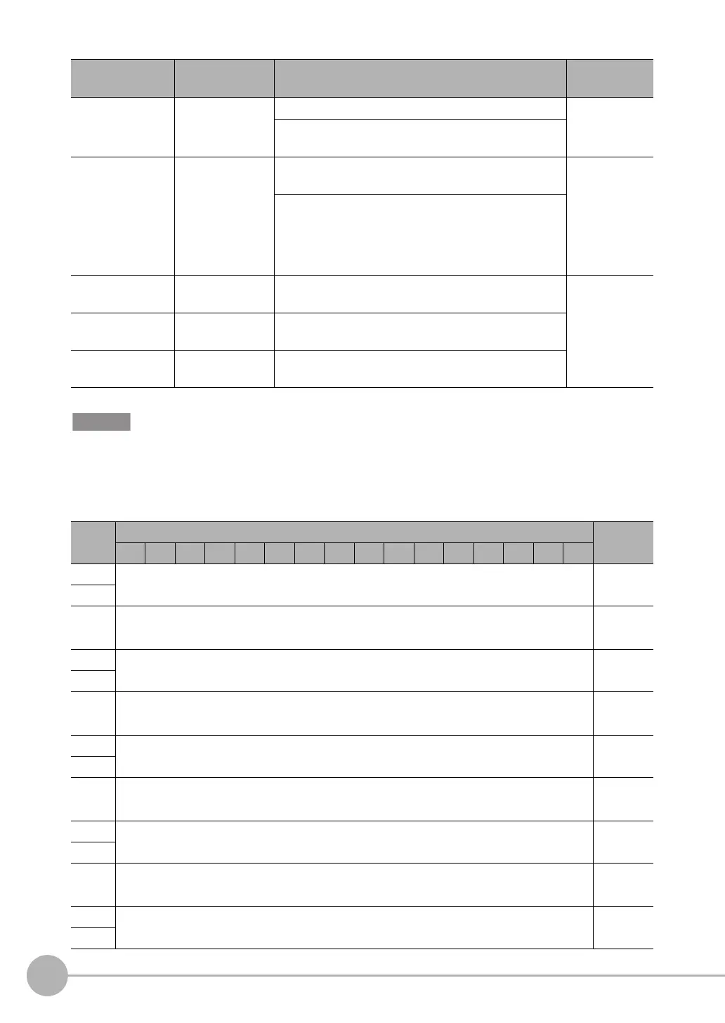
• Output Area
The output area is assigned immediately after the response area in I/O memory.
RUN Run Mode This signal is ON while the Vision Sensor is in Run Mode. Sensor status
change output
This signal is OFF while the Vision Sensor is not in Run
Mode.
GATE Data Output Com-
pleted
This signal turns ON when the Vision Sensor finishes out-
putting data.
Data output
after measure-
ments
If [Output handshake] is set to [Yes], this signal automati-
cally turns OFF when the Data Output Request Bit (DSA)
signal from the PLC turns OFF. If [Output handshake] is
set to [No], this signal turns OFF after the data output
period has elapsed.
Command code Command code This I/O port returns the command code that was exe-
cuted.
Command/
response com-
munications
Response code Response code This I/O port contains the response code of the executed
command.
Response data Response data This I/O port contains the response data of the executed
command.
Bits Contents
15 14 13 12 11 10 9 8 7 6 5 4 3 2 1 0
+8
DATA 0
Output data
0 (32 bits)
+9
·
·
·
·
·
·
·
·
·
+22
DATA 7
Output data
7 (32 bits)
+23
·
·
·
·
·
·
·
·
·
+38
DATA 15
Output data
15 (32 bits)
+39
·
·
·
·
·
·
·
·
·
+70
DATA 31
Output data
31 (32 bits)
+71
·
·
·
·
·
·
·
·
·
+134
DATA 63
Output data
63 (32 bits)
+135
Signal Signal name Function Application
method
FQ2-S_CH_comm.book 104 ページ 2014年6月26日 木曜日 午前11時47分

 Loading...


