Controlling Operation and Outputting Data with PLC Link Communications
126
FQ2-S/CH User’s Manual
for Communications Settings
[In/Out] − [I/O settings] − [Output data setting] − [Link data output/Fieldbus data output] −
[Output data set]
1 Press [0. Data 0].
2 Press [Multi-data].
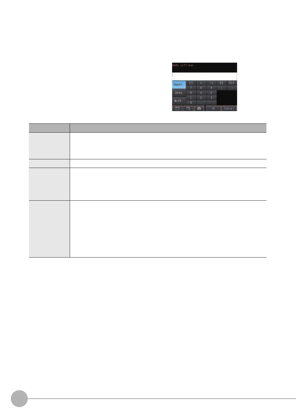
3 Set the following items on the display to set expres-
sions.
Item Description
Expression Register the expression to use to output multiple data.
Examples:
LPR (0, 3, I0.X, I0.Y)
LPC (0, I0.C, I0.X, I0.Y)
Const. Used to insert numbers and symbols into the expression.
Data Used to select the inspection items for which to output data and insert the parameters to output
into the expression.
Example: Selecting Parameters for the Search Item at Inspection Item 0
Inspection item: I0. Search
Judgement result: Judgement JG, Correlation: Corre. CR
Math. Either of the following two functions can be inserted.
• LPR function (order of the measurement data)
The measurement data is output in order.
Format: LPR(start_number,number_of_data,data_1, data_2,...data_5)
You can omit data 2 to data 5.
• LPC function (order of the detection points)
Data is output for each detected measurement point.
Format: LPC(start_number,number_of_data,data_1, data_2,...data_5)
You can omit data 2 to data 5.
To register something to data 1 and higher, repeat this process.
The settings will be enabled after you restart the Sensor.
FQ2-S_CH_comm.book 126 ページ 2014年6月26日 木曜日 午前11時47分

 Loading...


