Controlling Operation and Outputting Data with PLC Link Communications
130
FQ2-S/CH User’s Manual
for Communications Settings
● Response Area
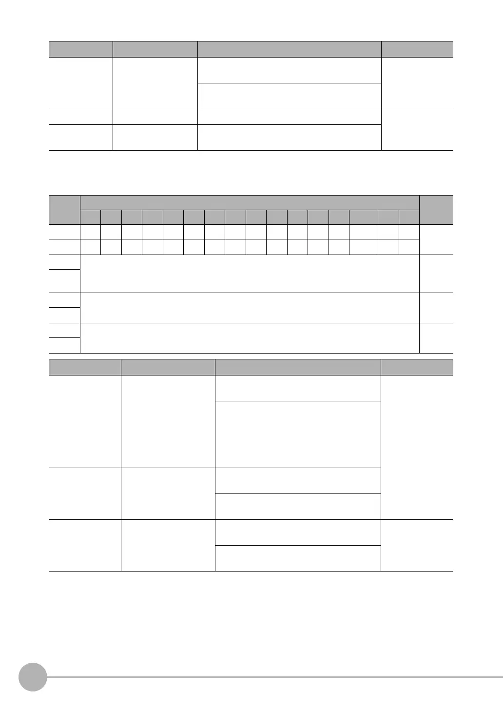
Vision Sensor (Slave) to PLC (Master)
ERRCLR Clear Error Turn ON this signal to turn OFF the error (ERR) sig-
nal from the Vision Sensor.
Command/
Response Commu-
nications
Turn OFF this signal from PLC when the error (ERR)
signal goes OFF.
Command code Command code This I/O port stores the command code. Command/
Response Commu-
nications
Parameters 1 to
3
Command parameters These I/O ports store the command parameters.
First
word
Bits Contents
15 14 13 12 11 10 9 8 7 6 5 4 3 2 1 0
+0 ERR Resv Resv Resv Resv Resv Resv Resv Resv Resv Resv Resv Resv READY
BUSY
FLG Control
signals
(32 bits)
+1 Resv Resv Resv Resv Resv Resv Resv Resv Resv Resv Resv Resv Resv Resv Resv
GATE
+2 Command code Com-
mand
code (32
bits)
+3
+4 Response code
Response
code (32
bits)
+5
+6 Response data
Response
data (32
bits)
+7
Signal Signal name Function Application
FLG Control Command Com-
pleted
This signal turns ON when the Vision Sensor
completes execution of the control command.
Command/
response commu-
nications
This signal automatically turns OFF when the
Control Command Execution Bit (EXE) signal
from the PLC turns OFF.
This signal turns ON after the control com-
mand code, response code, and response data
have been stored.
BUSY Command Execution
Active
This signal is ON while the Vision Sensor is
executing a control command.
It is OFF while the Vision Sensor is not execut-
ing a control command.
READY Trigger Input Ready This signal turns ON when the Vision Sensor
can execute a command.
Command/
response commu-
nications
This signal turns OFF when the Vision Sensor
cannot execute a command.
Signal Signal name Function Application
FQ2-S_CH_comm.book 130 ページ 2014年6月26日 木曜日 午前11時47分

 Loading...


