Controlling Operation and Outputting Data with PLC Link Communications
FQ2-S/CH User’s Manual
for Communications Settings
131
3
Controlling Operation and Outputting Data with an
Ethernet Connection
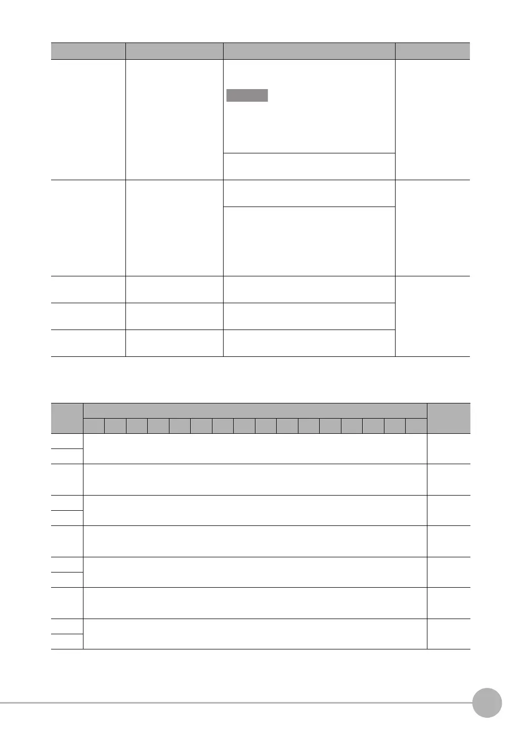
● Output Area
Vision Sensor (Slave) to PLC (Master)
ERR Error This signal turns ON when an error is detected
in the Vision Sensor.
This flag turns ON when an error occurs in
PLC link communications. This signal will
remain OFF for any errors other than PLC Link
communications errors.
Command/
response commu-
nications
This signal turns OFF when the Clear Error
(ERRCLR) signal from the PLC turns ON.
GATE Data Output Completed This signal turns ON when the Vision Sensor
finishes outputting data.
Data output after
measurements
When [Output handshake] is set to [Yes], this
automatically changes from ON to OFF when
the data output request signal (DSA signal)
from the user (PLC) changes from ON to OFF.
When [Output handshake] is set to [No], this is
the interval set in [Data output period].
Command code Command code This I/O port returns the command code that
was executed.
Command/
response commu-
nications
Response code Response code This I/O port contains the response code of the
executed command.
Response data Response data This I/O port contains the response data of the
executed command.
First
word
Bits Contents
15 14 13 12 11 10 9 8 7 6 5 4 3 2 1 0
+0
DATA 0
Output data
0 (32 bits)
+1
·
·
·
·
·
·
·
·
·
+14
DATA 7
Output data
7 (32 bits)
+15
·
·
·
·
·
·
·
·
·
+128
DATA 63
Output data
63 (32 bits)
+129
·
·
·
·
·
·
·
·
·
+512
DATA 255
Output data
255 (32 bits)
+513
Signal Signal name Function Application
FQ2-S_CH_comm.book 131 ページ 2014年6月26日 木曜日 午前11時47分

 Loading...


