Command Control
FQ2-S/CH User’s Manual
for Communications Settings
209
5
Appendices
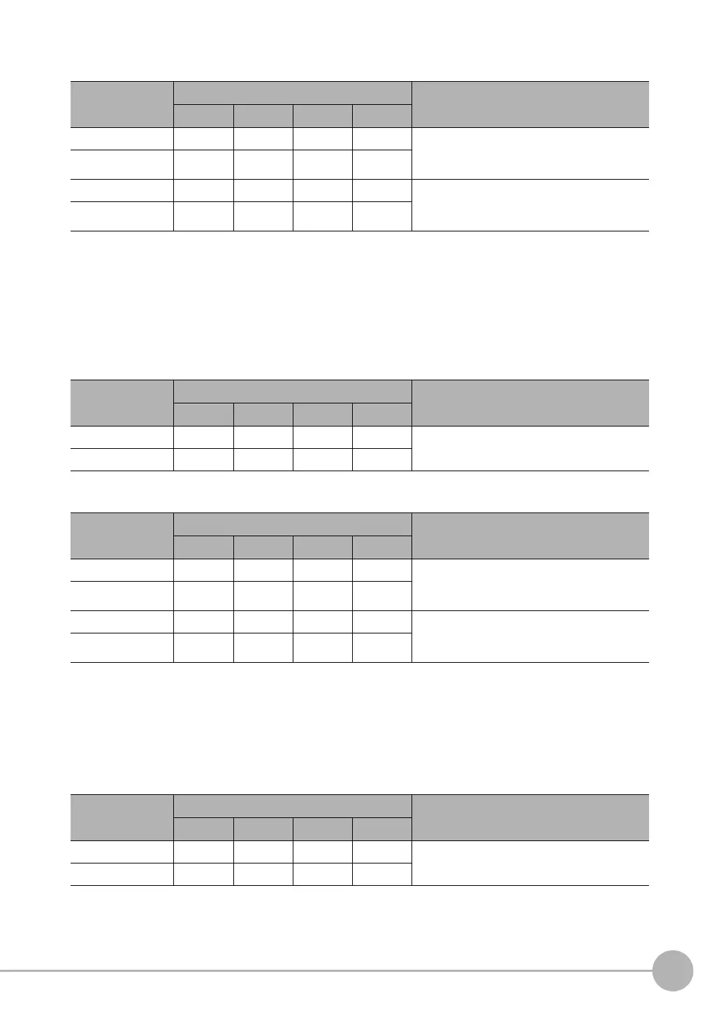
Response (Vision Sensor to PLC)
Clear Data Output Buffer
This command clears all data from the data output buffer of the Sensor. If an error occurs in the PLC after
measurement, data will remain in the data output buffer of the Sensor. This command clears the data. The
command prevents deviation of the data after an error occurs. This command only clears the data output buffer
of the Sensor; it does not clear the output area of the PLC.
Command (PLC to Vision Sensor)
Response (Vision Sensor to PLC)
Clear Statistical Data
This command clears the statistical data (such as the number of measurements, the number of NG overall
judgments, the NG rate, and other information since the power supply was turned ON) produced by the logging
function held by the Sensor.
Command (PLC to Vision Sensor)
First word of
response area
Bits Contents
12 to 15 8 to 11 4 to 7 0 to 3
+2 0010 0000 0001 0000 Command code
The command code for which the response
applies is stored.
+3 0000 0000 0001 0000
+4 0000 0000 0000 0000 Response code
Command execution result
0: OK, FFFFFFFF: NG
+5 0000 0000 0000 0000
First word of com-
mand area
Bits Contents
12 to 15 8 to 11 4 to 7 0 to 3
+2 0010 0000 0010 0000 Command code
+3 0000 0000 0001 0000
First word of
response area
Bits Contents
12 to 15 8 to 11 4 to 7 0 to 3
+2 0010 0000 0010 0000 Command code
The command code for which the response
applies is stored.
+3 0000 0000 0001 0000
+4 0000 0000 0000 0000 Response code
Command execution result
0: OK, FFFFFFFF: NG
+5 0000 0000 0000 0000
First word of com-
mand area
Bits Description
12 to 15 8 to 11 4 to 7 0 to 3
+2 0010 0000 0110 0000 Command code
+3 0000 0000 0001 0000
FQ2-S_CH_comm.book 209 ページ 2014年6月26日 木曜日 午前11時47分

 Loading...


