Control Methods Using an External Device
22
FQ2-S/CH User’s Manual
for Communications Settings
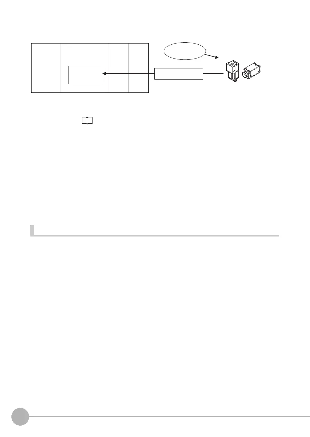
Flow of Communications between the PLC and the Sensor
The data to output after measurement and the PLC I/O memory area (Data Output Area) to store that data are
specified in advance. ( Setting Required for Data Output: p.61, 97, 124, 148, 169, 198.)
(1) Measurement is executed.
(2) After a measurement is executed, the specified measurement data is stored in the Data Output Area in
the PLC.
Parallel
A Parallel Interface Sensor Data Unit can be installed to enable data output.
The output data is output to the PLC signal wires via the D signals (D0 to D15).
This is only supported on the FQ2-S4/CH series.
No-protocol (TCP) Communications, No-protocol (UDP) Communications
The output data is output to the PLC reception buffer through non-procedure (normal) communications.
Items That Can Be Output as Output Data
Measurement Data
The following data items can be output by allocating measurement results and judgement results to output data
0 to output data 31.
• Judgement result
• Measured parameters (correlation values, reference coordinates, etc.)
• Results calculated based on the values of the measured parameters
• Judgement results from expression results (Parallel Judgement Output)
Character Output (This is Only Supported on the FQ2-S4/CH Series.)
After measurement, you can automatically output character strings that are read by OCR and other inspection
items to the PLC. Character strings can be output for the following inspection items.
•OCR
• Bar code
•2D-code
•2D-code (DPM)
Number of Characters That Can Be Output
The number of characters that can be output are shown below for each inspection item.
• OCR: Max. 128 characters
• Bar code, 2D-code, 2D-code (DPM): Max. 1024 characters
Data
Output Area
• Specified data is automatically output.
• Output characters
(2) Data
CPU Unit
PLC
I/O memory
(communications areas)
Sensor
Measurement
execution
(1)
FQ2-S_CH_comm.book 22 ページ 2014年6月26日 木曜日 午前11時47分

 Loading...


