Control Methods Using an External Device
28
FQ2-S/CH User’s Manual
for Communications Settings
Parallel Output of Measurement Data (Only Supported on the FQ2-S3/S4/CH Series)
When a Parallel Interface Sensor Data Unit is connected to the Sensor, the two types of data output below can
be performed, in addition to output of measurement judgement results.
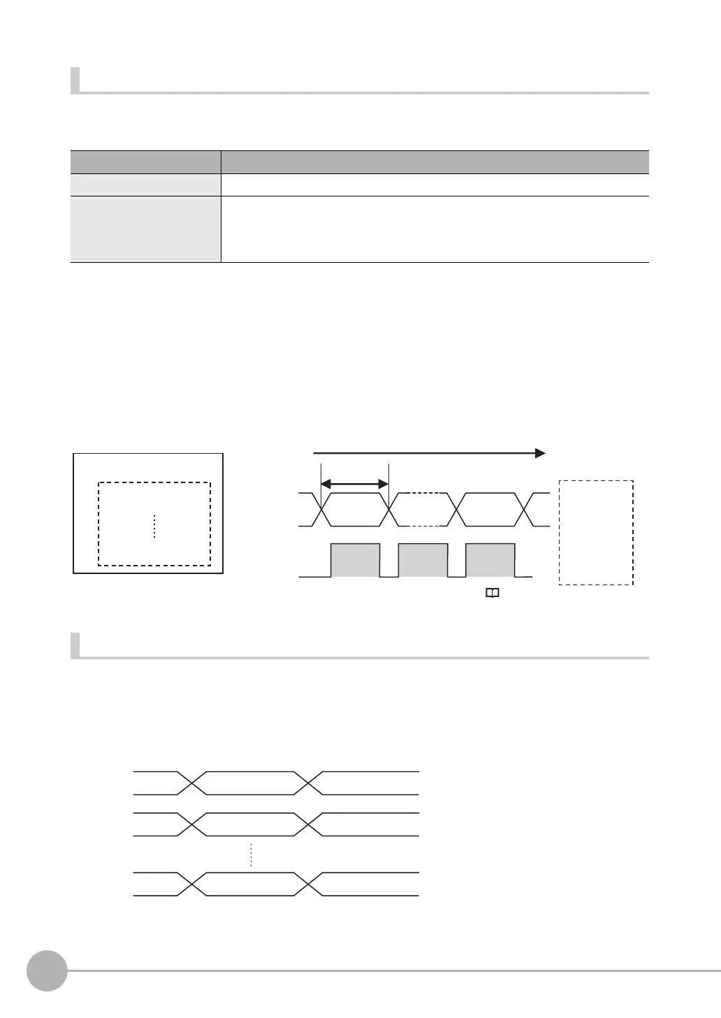
Order of Parallel Data Output
Parallel Output of Multiple Items
Items set to output numbers 0 to 31 of parallel data output are output by item (4 bytes) in ascending order to the
reception buffer of the PLC. The GATE signal turns OFF > ON
*1
at each output.
When this occurs, the first data item that was output to the PLC reception buffer (data 0) is overwritten by the
next output data item (data 1).
Therefore, the data output to the PLC reception buffer must be saved to PLC memory each time the GATE
signal turns ON for each data item.
*1: The operation of the DSA signal depends on whether handshaking for output control is enabled. Data Output Control with Handshak-
ing: p.30.
Data Output Timing
Output Sequence
If both parallel judgement output and parallel data output are performed at the same time, parallel judgement
output will be performed first followed by parallel data output.
Example: Parallel Judgement Output of D0 to D15 and Parallel Data Output of Data 0
Output data type Output data
Parallel Data Output The measurement data is output. A maximum of 32 items can be output.
Parallel Judgement Output The judgement results are output. A maximum of 16 judgement result items can be
output. The following two types of judgement results can be output:
• Judgement results for specified inspection items
• Judgement results of set judgement conditions for the specified item values
4 bytes
Parallel data output
PLC
0. Measurement data 0
31. Measurement data 31
Reception
buffer
Data output order
Measurement
data 31
Measurement
data 0
GATE
signal
D0 to D31
signals
ON
OFF
Parallel judgement
output D0
Parallel data output
(data 0)
Parallel judgement
output D1
Parallel data output
(data 0)
Parallel judgement
output D15
Parallel data output
(data 0)
D0
D1
D15
FQ2-S_CH_comm.book 28 ページ 2014年6月26日 木曜日 午前11時47分

 Loading...


