Controlling Operation and Outputting Data with the Sensor's Standard Parallel Connection
FQ2-S/CH User’s Manual
for Communications Settings
47
2
Controlling Operation and Outputting Data with a Par-
allel Connection
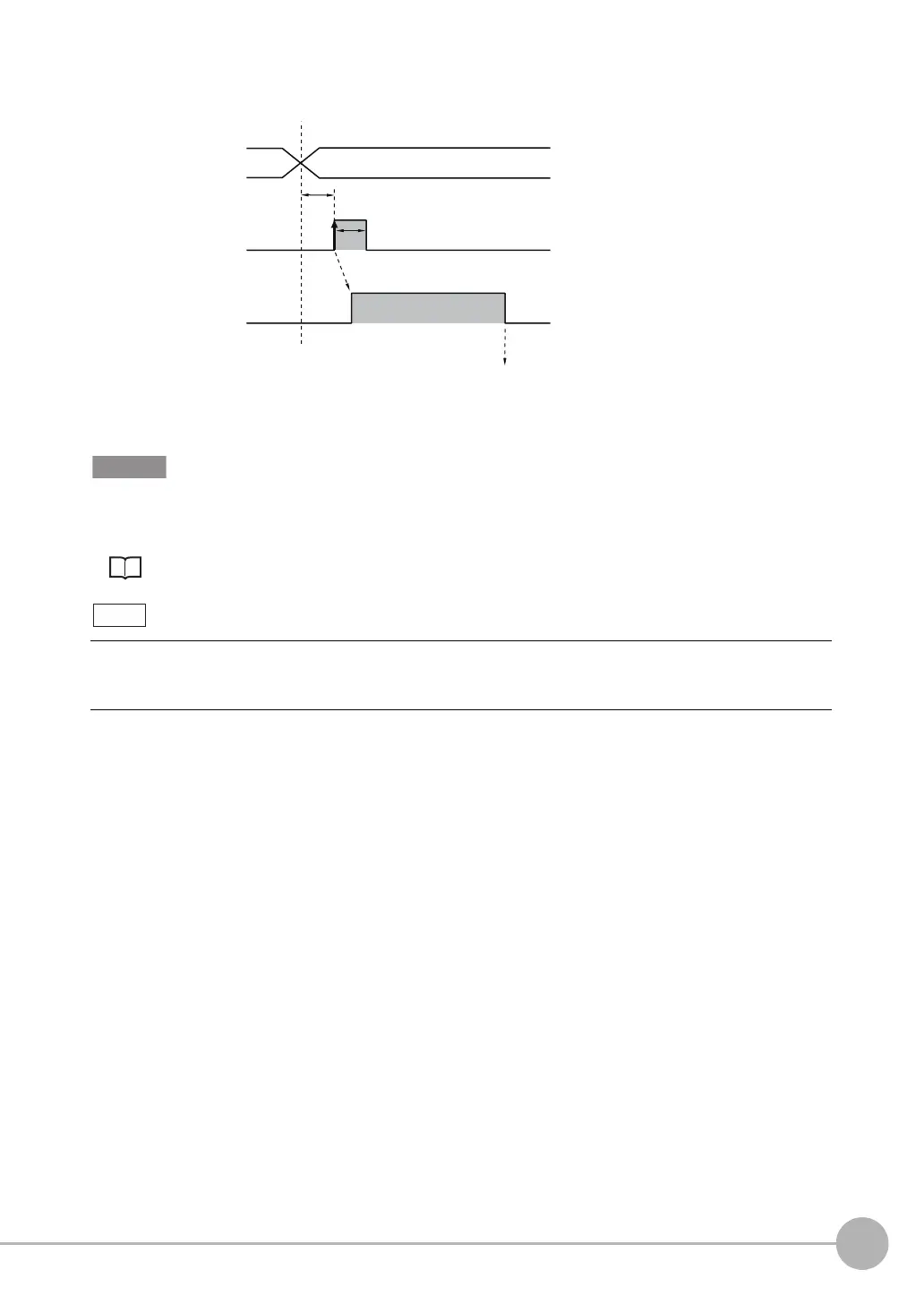
Timing Chart
The scene numbers that can be used depend on the input mode.
[Standard mode] (default): Scene 0 to 31
[Expanded mode]: Scene 0 to 15
Changing the Types of Commands That Can Be Used: p. 45
1 Specify the scene number
with the IN0 to IN4 signals.
(Standard Mode)
2 Turn ON the IN5 signal while
the BUSY signal is ON to
change the scene to the
specified scene.
3 The BUSY signal turns ON
while the scene is being
switched.
• Even in Expanded Mode, you can use menu commands or Ethernet no-protocol commands to change to scenes
0 to 31.
• The input mode can be set on both standard models and single-function models.
OFF
ON
OFF
ON
*1: In Expanded Mode, specify scene numbers 0 to 15 using the
IN0 to IN3 signals.
End scene change
Start scene change
BUSY signal
IN5 signal
ON for 1 ms min.
Allow 5 ms min. and then turn ON IN5.
Scene number 0 to 31
IN0 to IN4 signals
(in Standard Mode)
*1
FQ2-S_CH_comm.book 47 ページ 2014年6月26日 木曜日 午前11時47分

 Loading...


