Controlling Operation and Outputting Data with the Sensor's Standard Parallel Connection
FQ2-S/CH User’s Manual
for Communications Settings
53
2
Controlling Operation and Outputting Data with a Par-
allel Connection
Wiring
Timing Chart
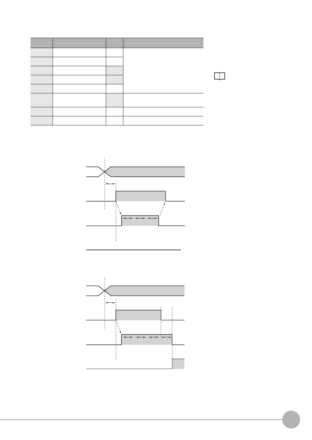
• When inspection is OK
• When inspection is NG
Color Signal State Description
The signals shown at the left
are used.
Refer to the following
information for signal wiring.
Section 2 Installation
and Connections
in Vision Sensor
FQ2-S/CH Series
User's Manual
(Cat. No. Z337)
Gray IN0 OFF Command parameters for trigger retry
(this command)
Green IN1 OFF
Red IN2 ON
White IN3 ON
Purple IN4 OFF
Ye l l o w I N 5 ON Command input for trigger retry (this com-
mand)
Orange OUT1 (BUSY) -- Busy
Black OUT0 (OR) -- Overall judgment (default)
1 IN0, IN1 and IN4 are turned OFF, IN2
and IN3 are turned ON.
2 When IN5 is turned OFF > ON with
the BUSY signal OFF, trigger retry
inspection starts.
3 When retry inspection starts, the
BUSY signal turns ON.
4 When the overall judgment turns ON,
retry inspection ends and the BUSY
signal turns OFF.
5 After verifying that the BUSY signal
has turned ON > OFF, IN5 is turned
ON > OFF.
1 IN0, IN1 and IN4 are turned OFF, IN2
and IN3 are turned ON.
2 When IN5 is turned OFF > ON with
the BUSY signal OFF, trigger retry
inspection starts.
3 When retry inspection starts, the
BUSY signal turns ON.
4 IN5 is turned OFF and retry inspection
ends. If retry inspection ends but the
overall judgment is NG, the OR signal
turns ON. (Output polarity: When ON
at NG)
OFF
ON
OFF
ON
OFF
ON
IN5 signal
IN0 to IN4 signals
IN5 ON after at least 5 ms
Retry starts
Scan
NG
Scan
NG
Scan
OK
Retry ends
BUSY signal
OR signal
OFF
ON
OFF
ON
OFF
ON
IN5 signal
IN0 to IN4 signals
IN5 ON after at least 5 ms
Retry starts
Scan
NG
Scan
NG
Scan
NG
Scan
NG
Retry ends
BUSY signal
OR signal
FQ2-S_CH_comm.book 53 ページ 2014年6月26日 木曜日 午前11時47分

 Loading...


