LD Cart Transporter User's Guide, 14766-000 Rev B
Page 102 of 190
Chapter 6: Connectivity
User Bumper
This connection is not used with a cart transporter.
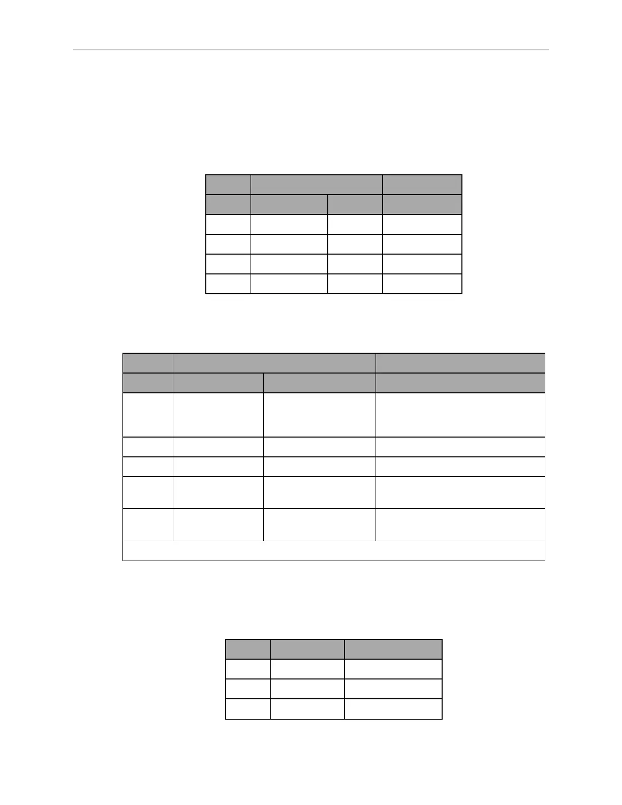
Aux Power
Connector type Mini-Fit
®
3 x 2
Designation
Pin No. Hardware Software Notes
1, 2, 3 GND
4 AUX_5V_OUT Aux_5V 5 V @ 1 A max
5 AUX_12V_OUT Aux_12V 12 V @ 1 A max
6 AUX_20V_OUT Aux_20V 20 V @ 1 A max
User Power
Connector type Mini-Fit
®
6 x 2
Designation
Pin No. Hardware Software Notes
1, 2,
3, 4,
5, 6
GND Limit to < 5 A per pin
7 SW_VBAT_OUT1 Battery_Out_1 VBAT @ 4 A max (switched in SW)
8 SW_VBAT_OUT2 Battery_Out_2 VBAT @ 4 A max (switched in SW)
9, 10* SW_VBAT_OUT34 Battery_Out_3_and_4 VBAT @ 10 A max (switched in SW).
Limit to < 5 A per pin.
11, 12* SAFE_VBAT_OUT SW_VBAT_OUT34 gated by
dual-channel ESTOP relays.
*9,10 and 11,12 share the 10 A of current.
Joystick
Connector type DB9F
Use Joystick
Pin No. Designation Notes
1 JOY_XAXIS Analog X input
2 JOY_YAXIS Analog Y input
3 JOY_SPEED Analog SPEED input