LD Cart Transporter User's Guide, 14766-000 Rev B
Page 91 of 190
Chapter 6: Connectivity
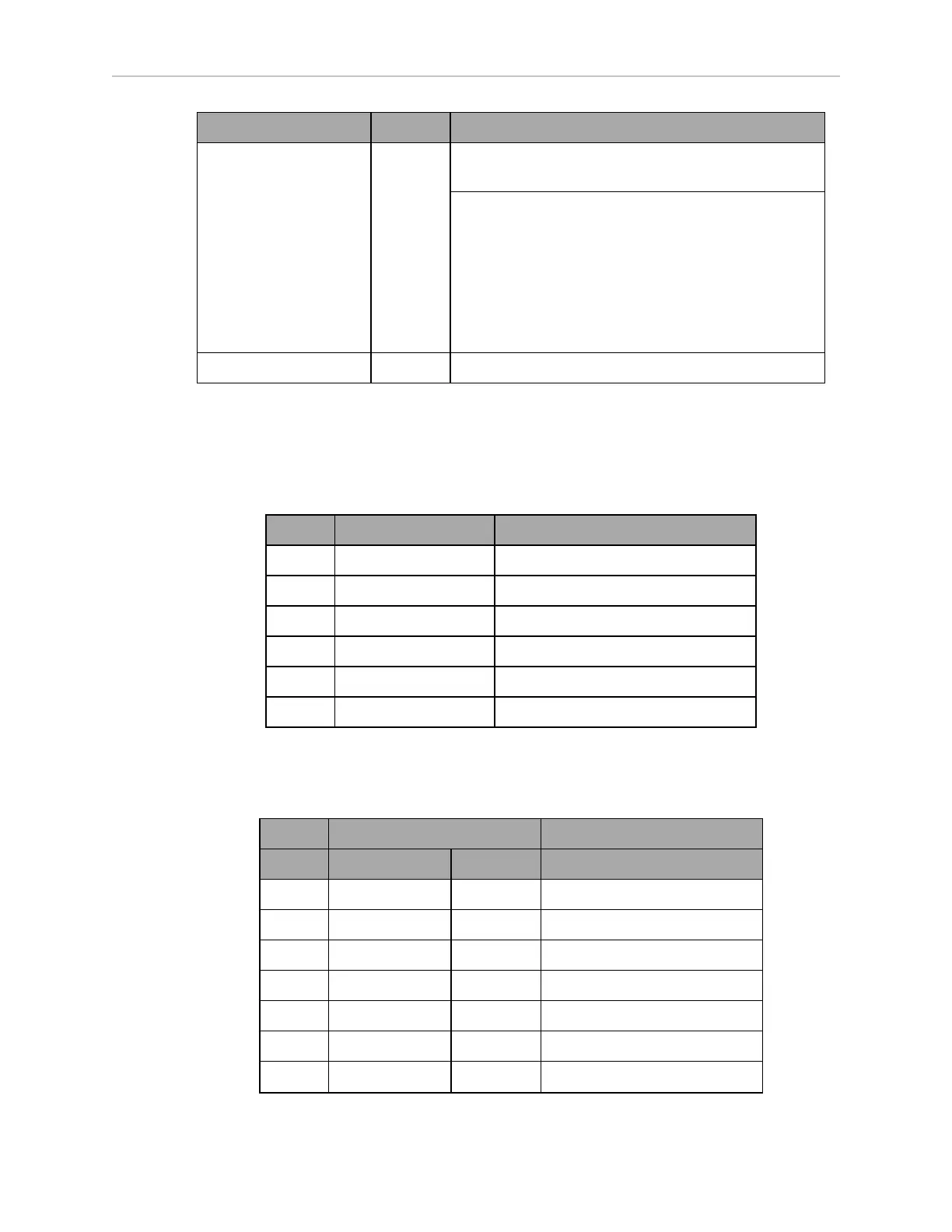
Connection Type Description
V
IN
range for each input is 0 to 30 V. The input is ON
when V
IN
> 4 V, OFF when V
IN
< 1.3 V.
16 digital outputs, protected low-side drivers. These
outputs should be wired to positive voltage through
the load. Output is open when OFF and grounded
when ON. Each open-drain output is capable of sink-
ing 500 mA. May be used with loads connected to
VBAT, AUX_20V, _12V, or _5V. You must stay
within the allowed current capacity of the VBAT or
AUX power supplies.
Analog I/O HDB15M General use
CAN Bus B
Connector type DB9F
Use CAN Bus
Pin No. Designation Notes
1, 4, 8 No Connection
2 CANL_B CAN Communication differential pair
3, 6 GND Direct GND
5 SHIELDGND Bead filter to GND
7 CANH_B CAN Communication differential pair
9 CANB_12V_OUT_SW 12 V @ 0.5 A Max (switched in SW)
Digital I/O
Connector type HDB44F
Designation
Pin No. Hardware Software Notes
1 INPUT_1.1 Input_1.1 0 – 30 V Range, R
in
= ~3.9 kΩ
2 INPUT_1.2 Input_1.2 0 – 30 V Range, R
in
= ~3.9 kΩ
3 INPUT_1.3 Input_1.3 0 – 30 V Range, R
in
= ~3.9 kΩ
4 INPUT_1.4 Input_1.4 0 – 30 V Range, R
in
= ~3.9 kΩ
5 BANK1 Common for INPUT_1.X
6 INPUT_2.1 Input_2.1 0 – 30 V Range, R
in
= ~3.9 kΩ
7 INPUT_2.2 Input_2.2 0 – 30 V Range, R
in
= ~3.9 kΩ