Installation notes Section 3-1
8
3-1 Installation notes
For improved reliability and maximized functionality, take the following
information into consideration when installing a NQ-Series HMI.
3-1-1 Location
Do not install the NQ-Series in the following locations:
• Areas subject to explosion hazards due to flammable gasses, vapours and
dusts.
• Areas subject to dramatic temperature changes. Temperature changes can
cause condensation of water in the device.
• Areas with an ambient temperature lower than 0 °C or higher than 50 °C.
• Areas subject to shock or vibration.
3-1-2 Temperature control
• Provide adequate space for air flow.
• Do not install the NQ-Series above equipment that generates significant
heat.
• If the ambient temperature exceeds 50 °C, install a cooling fan or air
conditioner.
3-1-3 Accessibility
• For safety during operation and maintenance, mount the NQ-Series as far
as possible from high-voltage equipment and power machinery.
3-1-4 Panel cut-out
Before the NQ-Series can be mounted, a rectangular cut-out must be made in
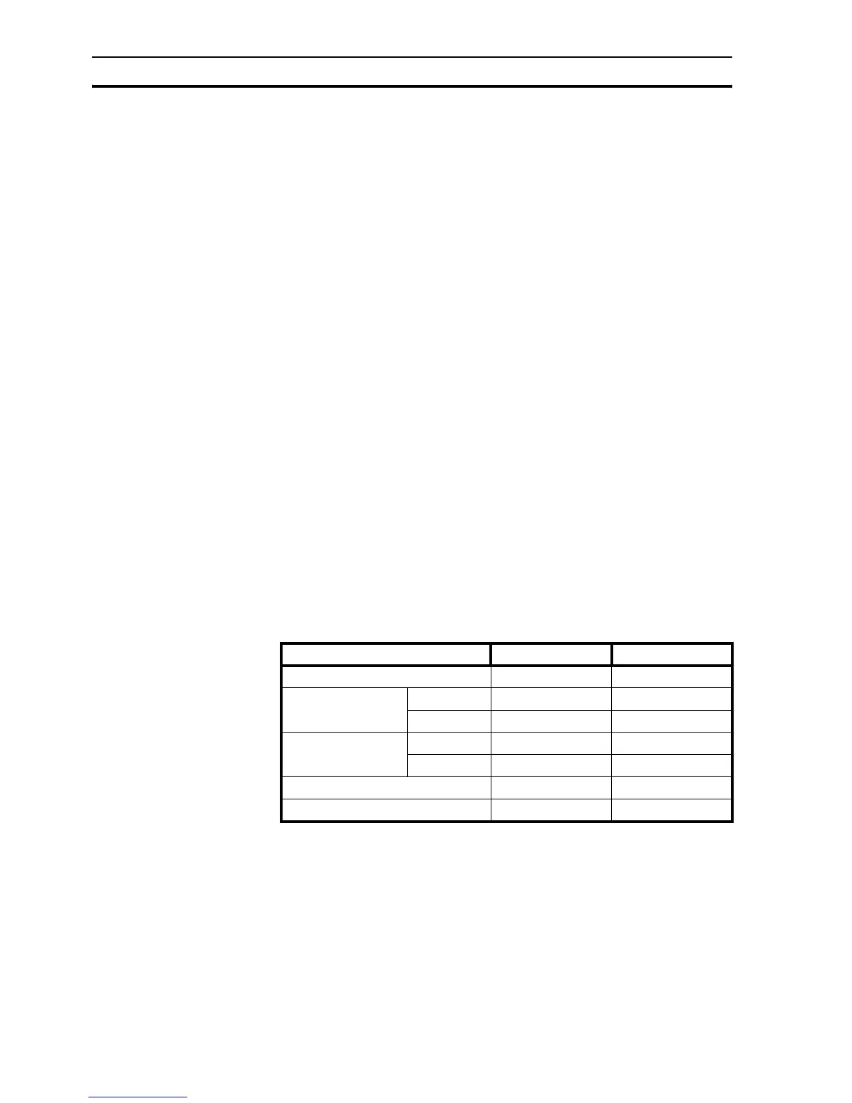
the panel in which the NQ-Series will be mounted. Table 3.1: Dimensions of
NQ-Series and required panel cut-out shows the dimensions and tolerances of
the NQ-Series, the panel and the required cut-out.
/i
Table 3.1: Dimensions of NQ-Series and required panel cut-out
Above external dimensions and cut-outs are for landscape models.
For portrait models exchange the W and H sizes. For portrait models the
cables will be mounted to the left side of the NQ-Series (view from front).
NQ5- NQ3-
Display size 5.7 “ 3.5 “ and 3.8 “
External dimensions: W
ext
195 mm 128 mm
H
ext
142 mm 102 mm
Panel cut-out: W
cut-out
184.00 mm 119.00 mm
H
cut-out
131.00 mm 93.00 mm
Panel cut-out tolerance +0.50 mm +0.50 mm
Panel thickness Max. 6.0 mm Max. 6.0 mm

 Loading...

