Wiring Section 3-3
12
3-3 Wiring
NQ-Series models have, besides one power connector, a number of
communication ports. Please refer to Table 2.2: Common specifications for
NQ-Series and Table 2.3: Specifications per NQ-Series model for the
availability of these ports on each of the NQ-Series models.
!Caution
If wiring is to be exposed to lightning or surges, use appropriate surge suppression
devices. Keep AC, high energy and rapidly switching DC wiring separate from signal
wires.
!WARNING Connecting high voltages or AC power mains to the DC input will make the NQ Series
unusable and may create an electrical shock hazard to personnel. Such a failure or
shock could result in serious personal injury, loss of life and/or equipment damage. DC
voltage sources should provide proper isolation from main AC power and similar
hazards.
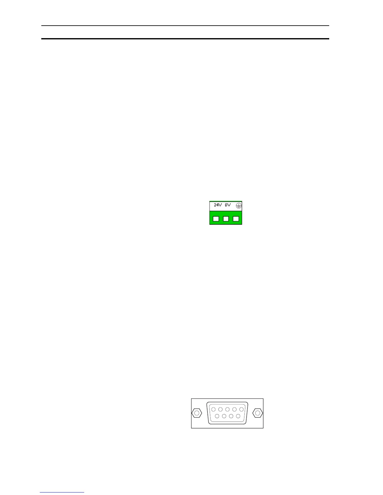
3-3-1 Power connector
All NQ-Series models have a 3-pin, Green coloured, power connector with pin
layout as shown in Figure 3.5: Power connector. Wire the inputs of the power
connector according to the pin layout, from left to right: +24 V
DC
(DC+), 0 V
(DC−) and Earth.
Figure 3.5: Power connector
3-3-2 Communication ports
The serial communication ports have two functions:
1 To connect to programming devices during configuration.
2 To communicate with a PLC and other devices in operating mode.
NQ-Series communication ports support various types of (serial)
communication.
3-3-2-1 COM1 port
COM1 is an integrated RS-232 and RS-485/RS-422 communication port. It
communicates with external peripherals devices at baud rates of 4800 kbps to
187.5 kbps with none, even or odd parity.
RS-485/RS-422 can be used in multi-drop (networks with more than one NQ-
Series or PLC) communication networks.
The connector is a standard D-type 9-pin female connector (see Figure 3.6: 9-
pin sub-D connector) with pin layout as shown in Table 3.2: Pin layout of port
COM1.
Figure 3.6: 9-pin sub-D connector
/i

 Loading...

