5-1 Connecting to Host Via Ethernet
5-14
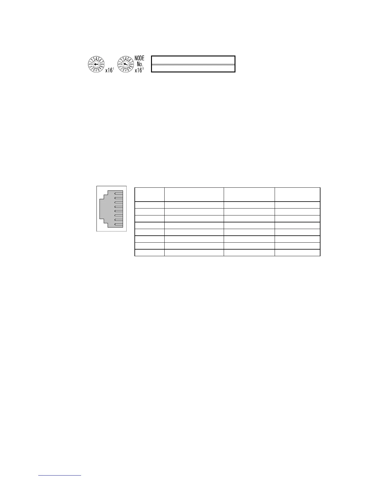
and 7E (1 to 126 decimal).
Setting range
01 to 7E (1 to 126 decimal)
Set the upper digit using the left rotary switch and the lower digit using the right rotary switch.
The factory setting is 01.
When using automatic generation to convert addresses, set the node number to the same
value as that of the rightmost byte of the local IP address. If the same values cannot be set,
the IP address table method or combination method must be used to convert the addresses.
Setting Local IP Addresses
Set the local IP address with the CX-Programmer or other computer support software. Refer
to the EtherNet/IP Unit Operation Manual (Cat. No. Z909) for details on setting methods.
Ethernet Connectors
This is the connector used to connect the twisted-pair cable to the Ethernet.
• Electrical Characteristics: Conforms to IEEE802.3 standards.
• Connector Layout: RJ45 8-pin modular connector (conforms to ISO8877).
Connec-
tor Pin
Signal name Abbreviation Signal direction
1 Send data TD+ Output
2
Send data − TD−
Output
3 Receive data + RD+ Input
4 Not used.
− −
5 Not used.
− −
6
Receive data − RD−
Input
7 Not used.
− −
8 Not used.
− −
• CP-series PLCs (Except for the CP1E)
CP-series Ethernet Option Board
CP1W-CIF41
Setting Node Numbers
Set the node number to a unique value. Do not set it to the same value as any other Ethernet
node on the same Ethernet network. Refer to the following manuals for the setting proce-
dures.
CP1H: SYSMAC CP Series CP1H CPU Unit Operation Manual (Cat. No. W450)
CP1L: SYSMAC CP Series CP1L CPU Unit Operation Manual (Cat. No. W462)
Setting Local IP Addresses
Use a Web browser to set the local IP address of the CP-series Ethernet Option Board.
Refer to the following manuals for the setting procedures.
CP1H: SYSMAC CP Series CP1H CPU Unit Operation Manual (Cat. No. W450)
CP1L: SYSMAC CP Series CP1L CPU Unit Operation Manual (Cat. No. W462)
1
8

 Loading...


