4-2 1:N Host Connection
4-26
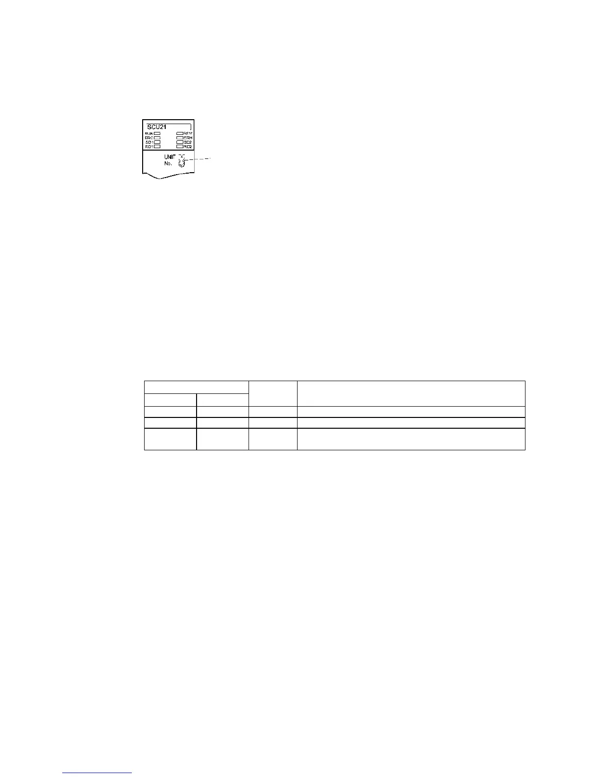
Setting the Front Panel Switches
Set the unit number of the Serial Communications Unit with the rotary switches on the front of
the Unit. Use a flat-blade screwdriver to set the numerals and symbols of the switch's setting
display window, as follows:
Connecting to CJ-series Serial Communications Units
CJ-series Units:
CJ1W-SCU41 (Port 1 is an RS-422A port and Port 2 is an RS-232C port.)
CPU Unit DM Area Settings
Write the settings directly from the Programming Device (Programming Console or CX-
Programmer) to the DM Area (Parameter Area) in the CPU Unit. After writing the settings,
enable the settings by turning ON the power again, restarting the Unit, restarting the commu-
nications port, or executing the CHANGE SERIAL PORT SETUP (STUP) instruction.
The following table shows the allocated DM Area words and settings.
The allocations and settings are the same for RS-232C and RS-422A.
m = 30000 + 100 × unit number
Allocated DM Area words
Port 1 Port 2
Write value Settings
DM m DM m + 10 8200 1:N NT Link Mode
DM m + 1 DM m + 11 000A Baud rate (high-speed)
DM m + 6 DM m + 16
000@@:Largest unit number (1 to 7) of the connected PTs. (See
note.)
Note: When connecting a single Unit in a 1:N connection, set the value of @ to 1 or higher.
Unit number setting
Set a value between 0 and F that is different from
that of any other Units in the system.
 Loading...


