Appendix 7 Preparing Connecting Cables for Bar Code Readers
A-23
Appendix 7 Preparing Connecting Cables for Bar
Code Readers
Refer to the following information when preparing the connecting cables for connecting the
V520-RH21-6 Bar Code Reader.
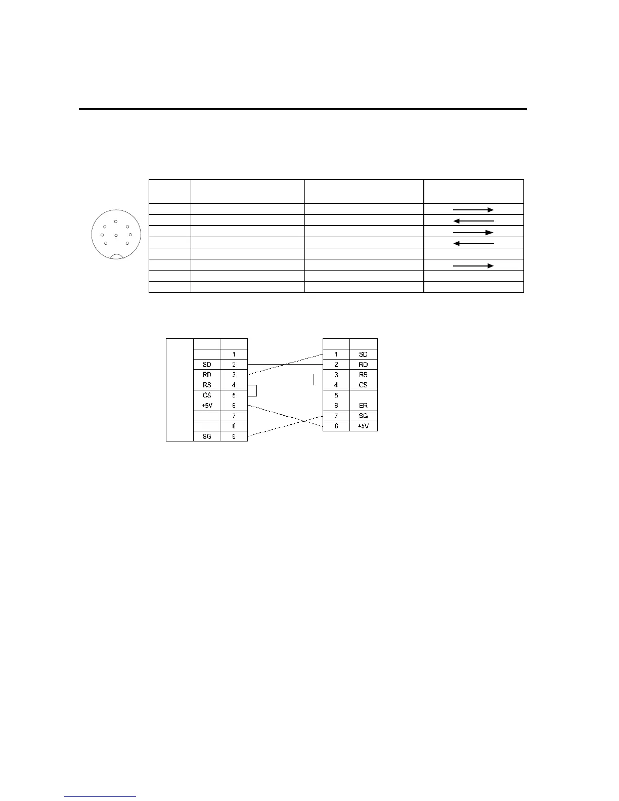
· Connector Pin Arrangement
Pin
number
Signal name Abbreviation
Signal direction
V520-RH21-6 PT
1 Send data SD (TXD)
2 Receive data RD (RXD)
3 Request to send RS (RTS)
4 Clear to send CS (CTS)
5 Not connected.
6 Data terminal ready ER (DTR)
70 V SG
8 Power supply (Vcc) +5 V
· Wiring Method
When connecting to the 5-V output of the PT’s serial port, use a cable length of less than
2 m. If the cable is 2 m or longer, connect pins 7 and 8 of the Bar Code Reader to an ex-
ternal power supply.
1
2
3
45
7
8
Connector pin
arrangement at
computer
PT
V520-RH21-6
RS-232C
interface
Signal Pin No. Signal Pin No.
6
 Loading...


