3-7 Installing the Video Input Unit
3-37
●Connecting to the Console Port Connector
Use the following method to connect the Video Board’s console port connector to the console
connector of an OMRON Vision Sensor (F150-C10V3, F160-C10, F180-C10, F400-C10V2,
F250-C10, V530-R150V2).
1.
Insert the socket of the Relay Cable (F150-VKP; see note) into the Video Board’s console
port connector.
Note The Relay Cable (F150-VKP) is the cable used to connect the Video Board’s console con-
nector to the console connector of an OMRON Vision Sensor.
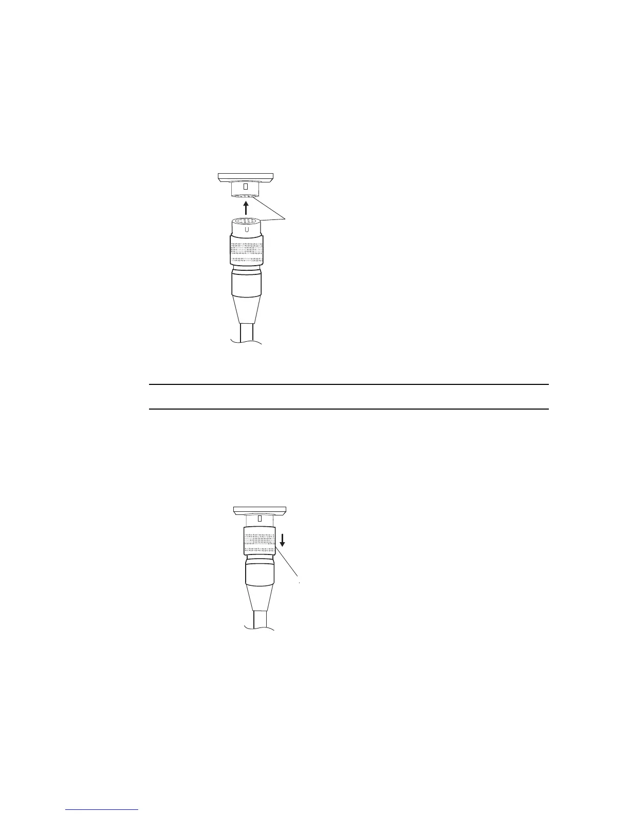
● Removing the Console Port Connector
Use the following method to remove the Relay Cable from the Video Board’s console port
connector.
1.
Remove the Relay Cable by pulling on the connector as shown below.
Console port connector
Pull here to unlock the
cable and remove it.
Relay cable
Align with groove and
insert.
Relay cable
The socket locks into place
when it is inserted.
Video Board's console
 Loading...


