3-8 Installing the Controller Link Interface Unit
3-52
2.
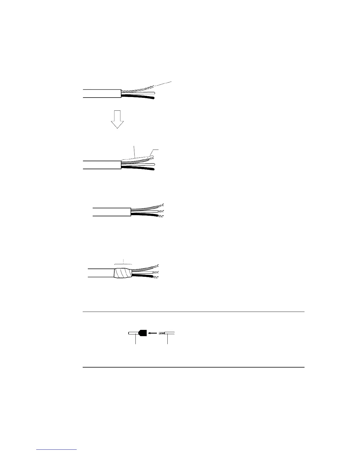
At the end connected to the node, twist the mesh of the shield into a single wire. Leave
sufficient length at the tip of the twisted shield to be connected to a crimp terminal and
cover the remaining section with heat-shrink tubing. Cut all the shield mesh off at the end
not connected to the node.
3. Strip the ends of the signal wires far enough to attach to the crimp terminals. Twist the
wire strands together.
4. Cover the end of the cable at the point it was stripped to in step 1 with vinyl tape or heat-
shrink tubing.
5. Attach crimp terminals to the shield wire and signal wires. Cover the connections with vi-
nyl tape or heat-shrink tubing.
Reference · We recommend the Phoenix AI-series crimp terminals shown in the following diagram.
Phoenix’s ZA3 crimping tool can be used to attach these terminals.
Cover with vinyl tape
or heat- shrink tubing.
Crimp terminal
Wire
Insert the wire and crimp the terminal to the wire.
Wire created by
twisting the shield
mesh.
Cover with heat-shrink tubing
Leave enough exposed wire to
attach to a crimp terminal.
 Loading...


