4-6
4-1 Monitor Mode
4
Functions
Fault Monitors 1 to 6 [d081] to [d086]
Displays the details of the last six trips.
The most recent trip is displayed on trip monitor 1.
(Display)
(1) Factor (Displays any of E01 to E79.)
*
(2) Output frequency (Hz) at the time of tripping
(3) Output current (A) at the time of tripping
(4) Main circuit DC voltage (V) at the time of tripping
(5) Total RUN time (h) before the trip
(6) Total power ON time (h) before the trip
* Refer to "Error Code List" (page 5-1).
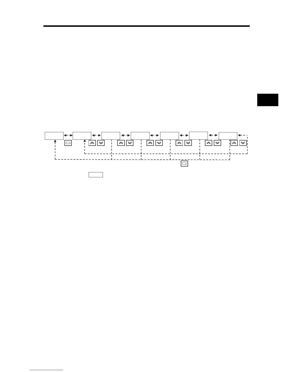
(Trip Monitor Display Sequence)
* Displays if there has been no trip.
Warning Monitor [d090]
•If the set data is inconsistent with other data, a warning code is displayed.
•While this warning remains in effect, the PROGRAM LED indicator (PRG) stays lit until forced to
rewrite or correct the data.
•For details on the Warning display, refer to "5-2 Warning Function".
DC Voltage Monitor [d102]
•Displays the DC voltage (between P and N) of the Inverter.
•During operation, the monitor value changes depending on the actual DC voltage of the Inverter.
(Display)
0.0 to 999.9: Displays in increments of 0.1 V.
Regenerative Braking Load Rate Monitor [d103]
Displays a regenerative braking load rate. When the monitor value comes close to exceeding the
value set in usage rate of the regenerative braking function b090, "E06 (Braking resistor overload
protection)" works to trip the Inverter.
(Display)
0.0 to 100.0: Displays in increments of 0.1%.
dk0k8k1 ek0k7.2 6k0.0k0 4.0k0 4k0k0.2 1k5.
1k8.
(1) Trip factor
*
(2) Trip frequency (3) Trip current (4) Trip main circuit
DC voltage
(5) Total RUN time (6) Power ON time
_k_k_k_