EasyManua.ls Logo

Omron S8M - User Manual

Omron S8M
158 pages
Print Icon
To Next Page IconTo Next Page
Loading...
At the end of this document you will find links to products related to this catalog. You can go directly to our shop by
clicking HERE. HERE

Table of Contents

Other manuals for Omron S8M

Questions and Answers

  • B
    Brian LopezSep 16, 2025
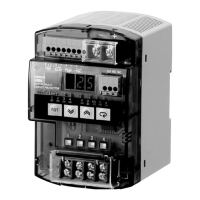
    Why is the desired alarm value not displayed on my Omron Surge Protector?
    • A
      Andrea JohnsonSep 16, 2025
      If the desired alarm value is not being displayed on your Omron Surge Protector, it is because the setting is not allowed in the present protection level. Change the protection level setting.
  • T
    Terrance JacksonAug 25, 2025
    Why is the Omron Surge Protector circuit cut off as soon as power is supplied?
    • P
      Patricia ProctorAug 25, 2025
      If your Omron Surge Protector circuit is cut off as soon as power is supplied, even though it wasn't designed for such a high current, the abnormal current tripping type might be set to 'instantaneous'. This setting detects abnormal current very quickly, potentially cutting off the circuit due to excessive current during equipment operation. You can either change the abnormal current tripping type from instantaneous to standard or raise the current tripping value. Alternatively, if there are a lot of devices connected to the output, which increases the operating current, use the S8M's startup sequence function to delay the connection of some devices.
  • R
    Roger GriffinAug 25, 2025
    How to clear alarm display on Omron Surge Protector?
    • W
      William WalkerAug 26, 2025
      If an alarm was triggered on your Omron Surge Protector and you've fixed the issue that caused it, but the alarm display won't clear, it's because the S8M retains the alarm display even after the problem is resolved. To clear the alarm, press the Reset Key for at least 3 seconds.
  • D
    davidhollowayAug 27, 2025
    What to do if the Omron Surge Protector output is cut off immediately in Test Mode?
    • M
      Melinda RuizAug 27, 2025
      If the Omron Surge Protector output is connected in Test Mode, but it's cut off immediately and can't be reconnected, check the status indicator to see if it's lit red. This indicates the current may be higher than the tripping current. Look for output wiring problems. If no problems are found, press the Reset Key for at least 3 seconds.
  • L
    lisa49Sep 18, 2025
    Why does the Omron Surge Protector display “- - -” for peak output current?
    • D
      david40Sep 18, 2025
      If the peak output current is not displayed and the display shows “- - -” on your Omron Surge Protector, it is because the current may have exceeded the measurable range. Clear the peak output current in Run Mode.
  • R
    Rose RiveraSep 23, 2025
    How to enable branch outputs on Omron Surge Protector?
    • H
      Heather StevensonSep 23, 2025
      If the branch outputs of your Omron Surge Protector are not working, it is because all branch outputs are disconnected in the default settings to ensure safety. Switch to Test Mode and connect the desired branch outputs.
  • L
    Lisa FrancisSep 8, 2025
    Why does the Omron Surge Protector output cut off immediately after being reset?
    • S
      Stephanie GuerreroSep 9, 2025
      If the output was reset on your Omron Surge Protector, but it was immediately cut off again, it means that the original cause of the cut-off may not have been eliminated. Eliminate the problem that caused the cutoff and press the Reset Key for at least 3 seconds.
  • B
    Brittany HamiltonSep 9, 2025
    How to clear the run time alarm on Omron Surge Protector?
    • C
      christina93Sep 10, 2025
      If the run time alarm was output on your Omron Surge Protector, so the equipment was checked and other parts were replaced, but the alarm could not be cleared, it is because the S8M continues adding to the run time. Clear the run time and then press the Reset Key for at least 3 s. The alarm can also be cleared by increasing the run time value and then resetting.
  • J
    jramirezSep 3, 2025
    What to do if alarm output went OFF and cannot be cleared on Omron Surge Protector after setting overvoltage and undervoltage alarms?
    • K
      katie64Sep 3, 2025
      If the S8M was switched to Run Mode after setting the overvoltage alarm and undervoltage alarm, and the alarm output went OFF and cannot be cleared on your Omron Surge Protector, the undervoltage and overvoltage settings may have been reversed. Switch to Setting Mode and check the settings.
  • G
    Grant SantosSep 1, 2025
    What to do if Omron Surge Protector display is flashing 'ON' in Test Mode but no power is supplied?
    • J
      Jeffrey DavisSep 1, 2025
      If the Omron Surge Protector display is flashing “ON” in Test Mode, but power isn't being supplied by the outputs, it means the S8M is waiting to turn ON the outputs. Pressing the Mode Key will connect the output and supply power. When power is being supplied, “OFF” will flash on the display.

Summary

SECTION 1 Features and Functions

1-1 Overview of Features and Functions

Introduces the S8M's features, digital processing, and advantages over mechanical protectors.

1-2 S8 M Operations and Operating Modes

Explains the three operating modes (Run, Setting, Test) and how to switch between them.

1-3 Table of Basic Functions

Summarizes tripping and alarm functions, external outputs, and input specifications.

1-4 S8 M Operating Procedure

Outlines typical startup procedures using keys or the support tool.

SECTION 2 Specifications and Functions

2-1 Component Names and Functions

Identifies and describes the S8M's physical components and their functions.

2-2 Internal Configuration

Provides block diagrams showing the internal circuitry of different S8M models.

2-3 Specifications

Lists detailed electrical and environmental ratings and characteristics for S8M models.

2-4 Basic Function Details

Explains core functions like current protection, over/undervoltage alarms, and over-temperature output.

2-5 Startup Sequence Function

Describes the function that applies a time delay to branch output connections upon startup.

2-6 Shutdown Sequence Function

Details the function that applies a time delay to branch output cutoffs.

SECTION 3 Installation and Wiring

3-1 Installation Environment

Specifies precautions for selecting an installation site and maintaining ambient conditions.

3-2 Installation

Provides instructions for mounting the S8M on a DIN rail and its correct orientation.

3-3 Wiring

Details wiring precautions, recommended wire types, and torque specifications for terminals.

3-4 RS-232 C Port Wiring (S8 M-CP04-R and S8 M-CP04-RS Only)

Explains how to create and connect cables for RS-232C communication.

SECTION 4 Parameter Settings

4-1 Parameter Table

Presents a comprehensive table of all settable parameters, their display, and access levels.

4-2 Parameter Setting Ranges

Lists the setting ranges and default values for each S8M parameter.

4-3 Switching the Operating Mode

Describes how to navigate the Mode Selection Menu and switch between modes.

4-4 Changing the Protection Level

Explains how to change the protection level to restrict parameter access.

4-5 Switching to Setting Mode

Details the procedure to enter Setting Mode from Run or Test Mode.

4-6 Individual Branch Output Settings

Guides users through setting parameters specific to each branch output.

4-7 Shared Parameter Settings

Covers parameters that apply across multiple branches, like alarms and run time.

4-8 Special Settings and Communications Settings

Explains settings for startup/shutdown sequences, tripping inputs, and communication.

SECTION 5 Trial Operation to Actual Operation

5-1 Test Mode

Explains how to use Test Mode for checking branch output connections before operation.

5-2 Connection;Disconnection Test

Details the procedure for testing and manually connecting/disconnecting branch outputs.

5-3 Checking Sequence Operation

Describes how to verify the startup and shutdown sequence operations.

5-4 Run Mode

Explains how to operate the S8M in Run Mode and monitor various parameters.

SECTION 6 Support Tool

6-1 Installing the Support Tool

Guides users through downloading and installing the S8M Support Tool software.

6-2 Starting the Support Tool

Explains how to launch the Support Tool and navigate its interface.

6-3 Setting and Saving Parameters

Details how to configure, save, and download parameters using the Support Tool.

6-4 Monitoring

Describes how to monitor the S8M's operating status using the Support Tool.

6-5 Other Settings

Covers configuring communications settings and protection levels via the Support Tool.

SECTION 7 Communications

7-1 CompoWay;F Communications Specifications

Outlines the communication specifications and methods used by the S8M.

7-2 Frame Structure

Explains the structure of command and response frames for S8M communication.

7-3 Details of Services

Describes available communication services like reading data and executing commands.

7-4 Read Controller Information

Details the service for reading the controller's model and version information.

7-5 Read Controller Attributes

Explains how to read the model number and communications buffer size.

7-6 Read Controller Status

Describes the service for reading the S8M's operating and error status.

7-7 Echoback Test

Explains the procedure for performing an echoback test for communication verification.

7-8 Operation Command

Details the commands for controlling S8M operations like connect, disconnect, and reset.

7-9 Response Code List

Provides a list of response codes and their meanings for communication errors.

7-10 ASCII List

Lists ASCII character codes for communication data.

SECTION 8 Error Processing

8-1 Troubleshooting

Offers solutions for common observed problems encountered during S8M operation.

8-2 Seven-segment Error Codes

Lists and explains error codes displayed on the S8M's seven-segment display.

8-3 Clearing Errors

Provides instructions on how to clear errors using the Reset Key or Support Tool.

Appendix A Glossary

Glossary

Defines key terms and concepts related to the S8M Digital Multicircuit Protector.

Appendix B List of Operations

Mode Selection Menu Operations

Illustrates the menu flow for navigating between different operating modes.

Revision History

Omron S8M Specifications

General IconGeneral
BrandOmron
ModelS8M
CategorySurge Protector
LanguageEnglish