Chapter 2
2-20
Standard Models and Specifications
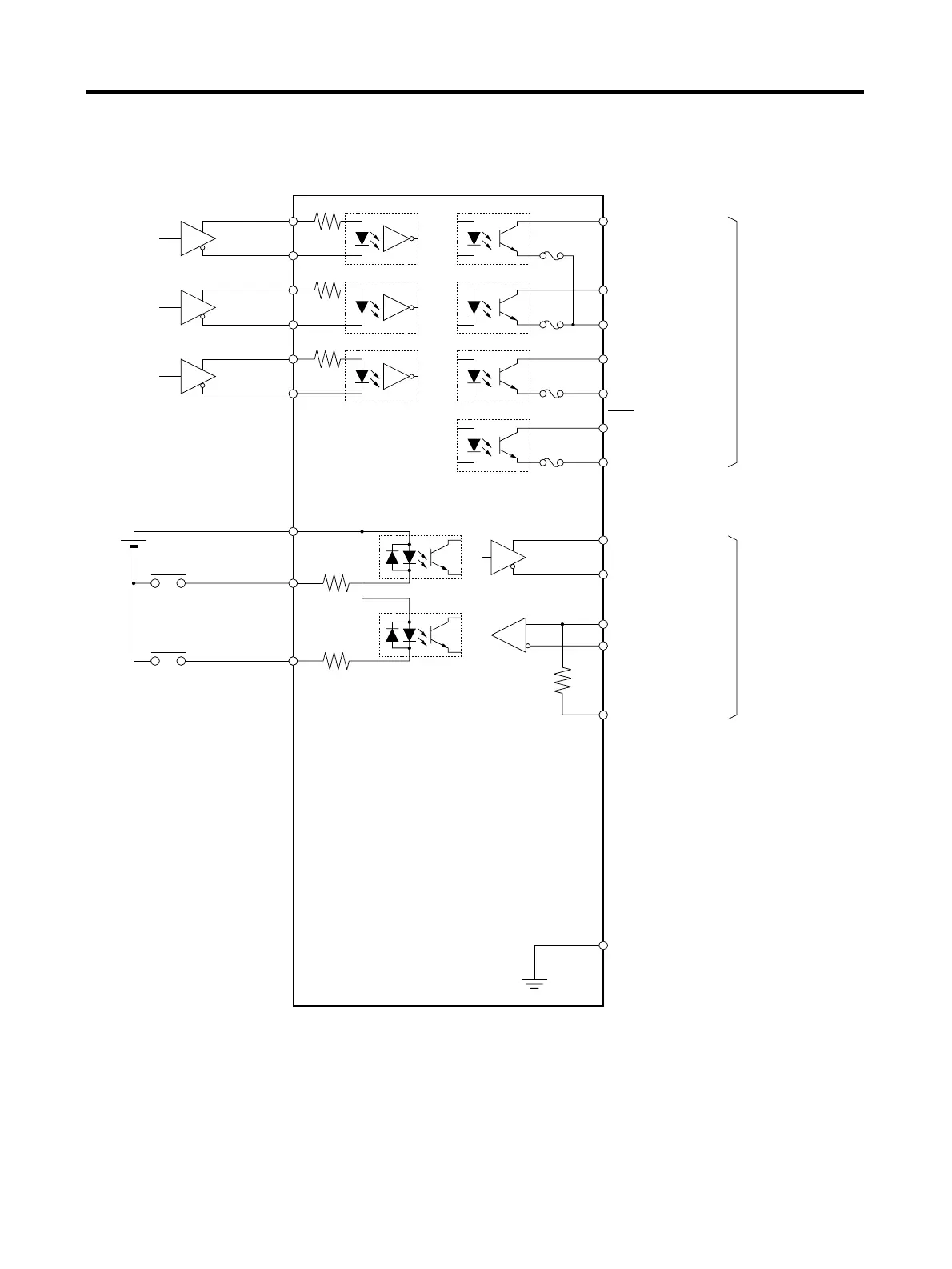
2-3-4 Control I/O Specifications (CN1)
■ Control I/O and External Signals for Position Control
Note 1. Interface for RS-422:
• Applicable line driver: T.I. SN75174, MC3487 or equivalent
• Applicable line receiver: T.I. SN75175, MC3486 or equivalent
Note 2. Automatic-reset fuses are used for output protection. If overcurrent causes the fuse to oper-
ate, current will not flow, and after a fixed period of time it will automatically reset.
Maximum operating
voltage: 30 V DC
RUN command
Alarm reset
Reverse pulse
Forward pulse
Deviation
counter reset
Positioning
completed output
Frame ground
Shell
200 Ω
4
5
6
200 Ω
200 Ω
+CW
−CW
+CCW
−CCW
+ECRST
−ECRST
1
2
3
INP8
OGND
BKIR7
10
18RESET
3.3 k
14RUN
13
+24VIN24 V DC
FG
(See note 1.)
3.3 k
ZCOM
Z32
33
ALMCOM
ALM34
35
22
23 TXD−
TXD+
20 RXD+
21 RXD−
24 RT
(See
note 2.)
(See
note 2.)
(See
note 2.)
(See
note 2.)
Maximum Output
Current:
Phase Z: 20 mA DC
Other than Phase Z:
50 mA DC
Brake interlock
Phase Z
Alarm output
Transmission data
Reception data
Terminating
resistance terminal