Chapter 3
3-37
System Design and Installation
3-3 Regenerative Energy Absorption
The Servo Drivers have internal regenerative energy absorption circuitry for absorbing
the regenerative energy produced during time such as Servomotor deceleration, and
thus preventing the DC voltage from increasing. An overvoltage error is generated,
however, if the amount of regenerative energy from the Servomotor is too large. If this
occurs, measures must be taken to reduce the regenerative energy produced by
changing operating patterns, and so on, or to improve the regenerative energy
absorption capacity by connecting external regeneration resistance.
3-3-1 Regenerative Energy Calculation
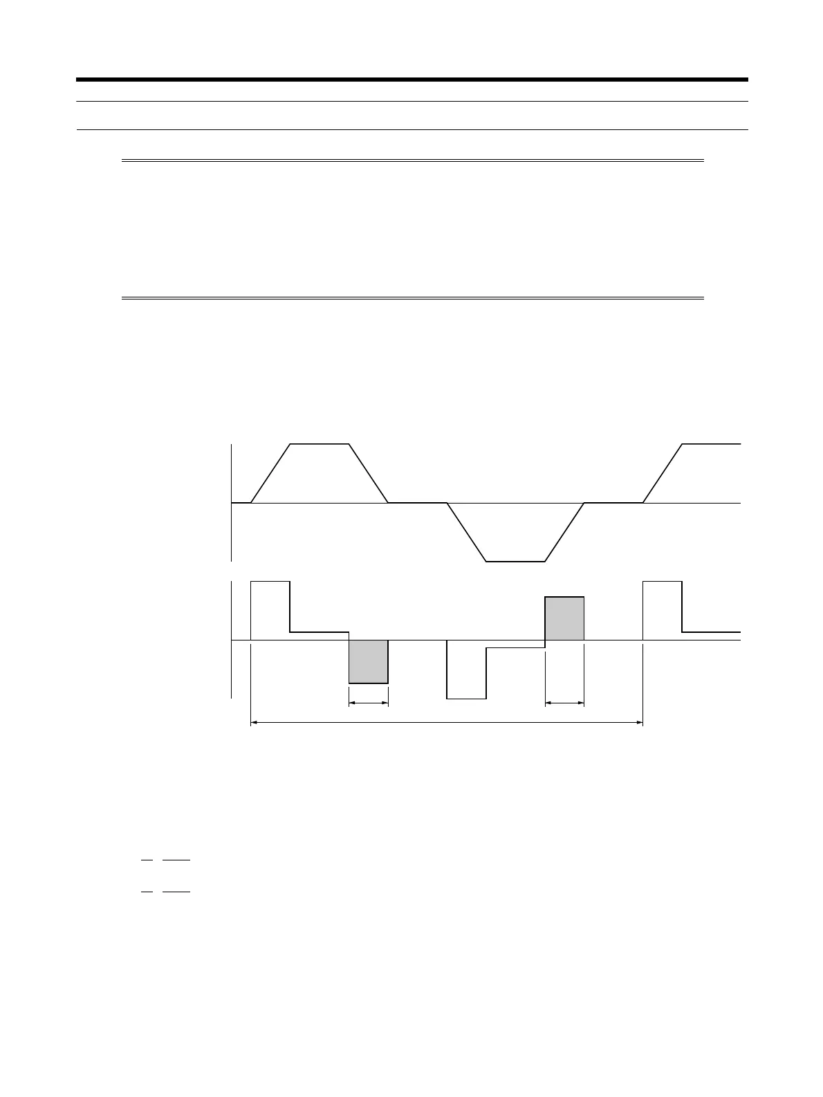
■ Horizontal Axis
Note In the output torque graph, acceleration in the positive direction is shown as positive, and
acceleration in the negative direction is shown as negative.
• The regenerative energy values for E
g1
and E
g2
are derived from the following equations.
Servomotor operation
Servomotor output torque
+N1
−N2
TD1
TD2
t1 t2
T
E
g1
Eg2
N1, N2: Rotation speed at beginning of deceleration [r/min]
T
D1, TD2: Deceleration torque [N·m]
t
1, t2: Deceleration time [s]
• Eg1 = • • N1 • TD1 • t1 [J] = 0.0524 • N1 • TD1 • t1 [J]
260
60
2π
2π
1
• E
g2 = • • N2 • TD2 • t2 [J] = 0.0524 • N2 • TD2 • t2 [J]
2
1