Chapter 1
1-5
Introduction
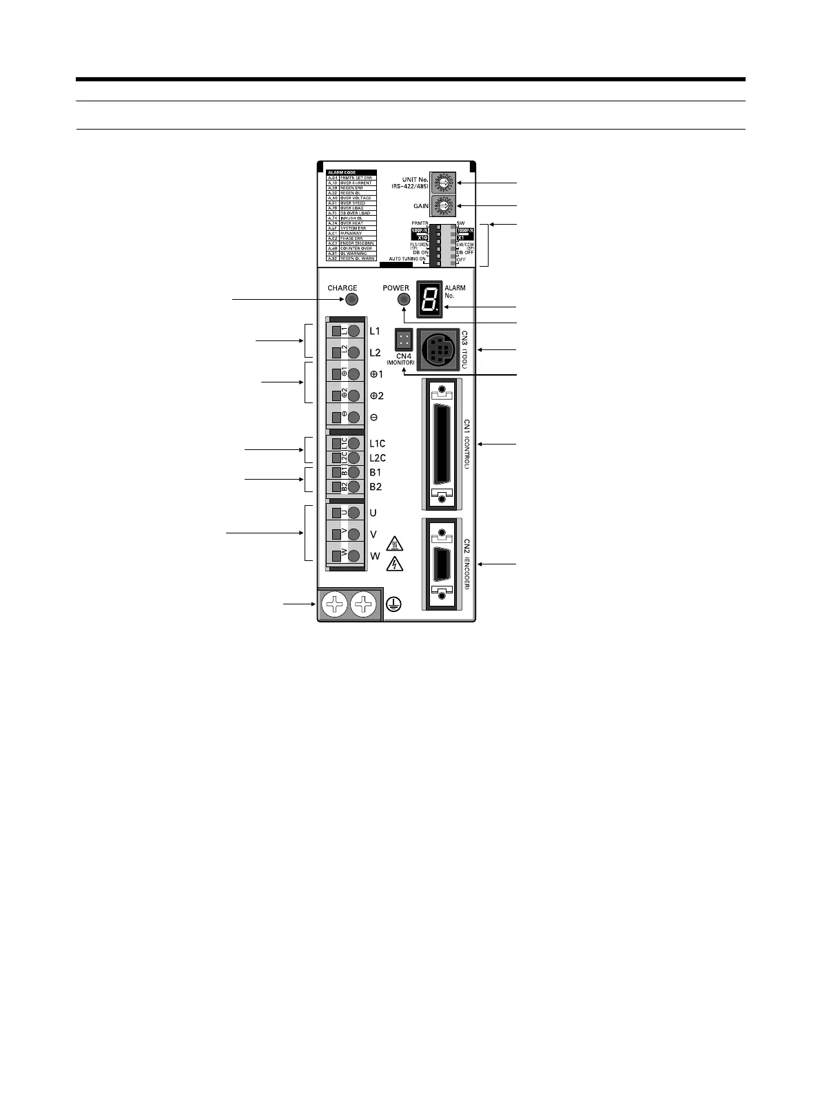
1-3 Servo Driver Nomenclature
Rotary switch for unit No. selection
Rotary switch for gain adjustment
Function selection switches:
Alarm display
Control-circuit power supply indicator
Communications connector (CN3)
Monitor output connector (CN4)
Control I/O connector (CN1)
Encoder input connector (CN2)
Main-circuit power supply
indicator
Main-circuit power
supply input terminals
DC reactor connection terminals
Control-circuit power supply
input terminals
Servomotor power terminals
FG terminals for power supply and
servomotor power
External regeneration
resistance terminals
• Switch/parameter setting enable switch
• Resolution setting
• Command pulse input setting
• Dynamic braking setting
• Online autotuning switch