Chapter 3
3-19
System Design and Installation
4. Insert the wire into the slot.
With the slot held open, insert the end of the wire. Then let the slot close by releasing the pressure
from the lever or the screwdriver.
5. Mount the Terminal Block to the Servo Driver.
After all of the terminals have been wired, return the Terminal Block to its original position on the
Servo Driver.
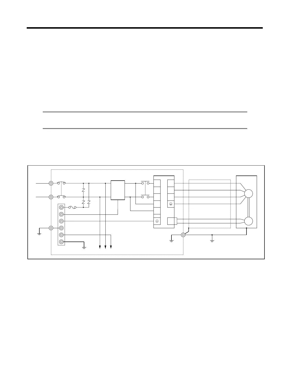
3-2-4 Wiring for Noise Resistance
System noise resistance will vary greatly depending on the wiring method used. This
section explains how to reduce noise through proper wiring.
■ Wiring Method
● Single-phase Power Supply Input
NFB
AC power
supply
Surge absorber
Noise filter
Contactor
X1
Metal duct
Fuse
Class D ground
(Class 3 ground:
100 Ω or less)
Controller power supply
Thick power line (3.5 mm
2
)
Machine ground
Ground plate
Ground control box
3.5 mm
2
1
2
3
4
E
NF
TB
L1
L2
L1C
L2C
U
V
W
TB
CN2
R7D-AP@ R7M-A@
E
M
2 mm
2