Chapter 3
3-15
System Design and Installation
3-2-3 Terminal Block Wiring
When wiring a Terminal Block, pay attention to wire sizes, grounding systems, and anti-
noise measures.
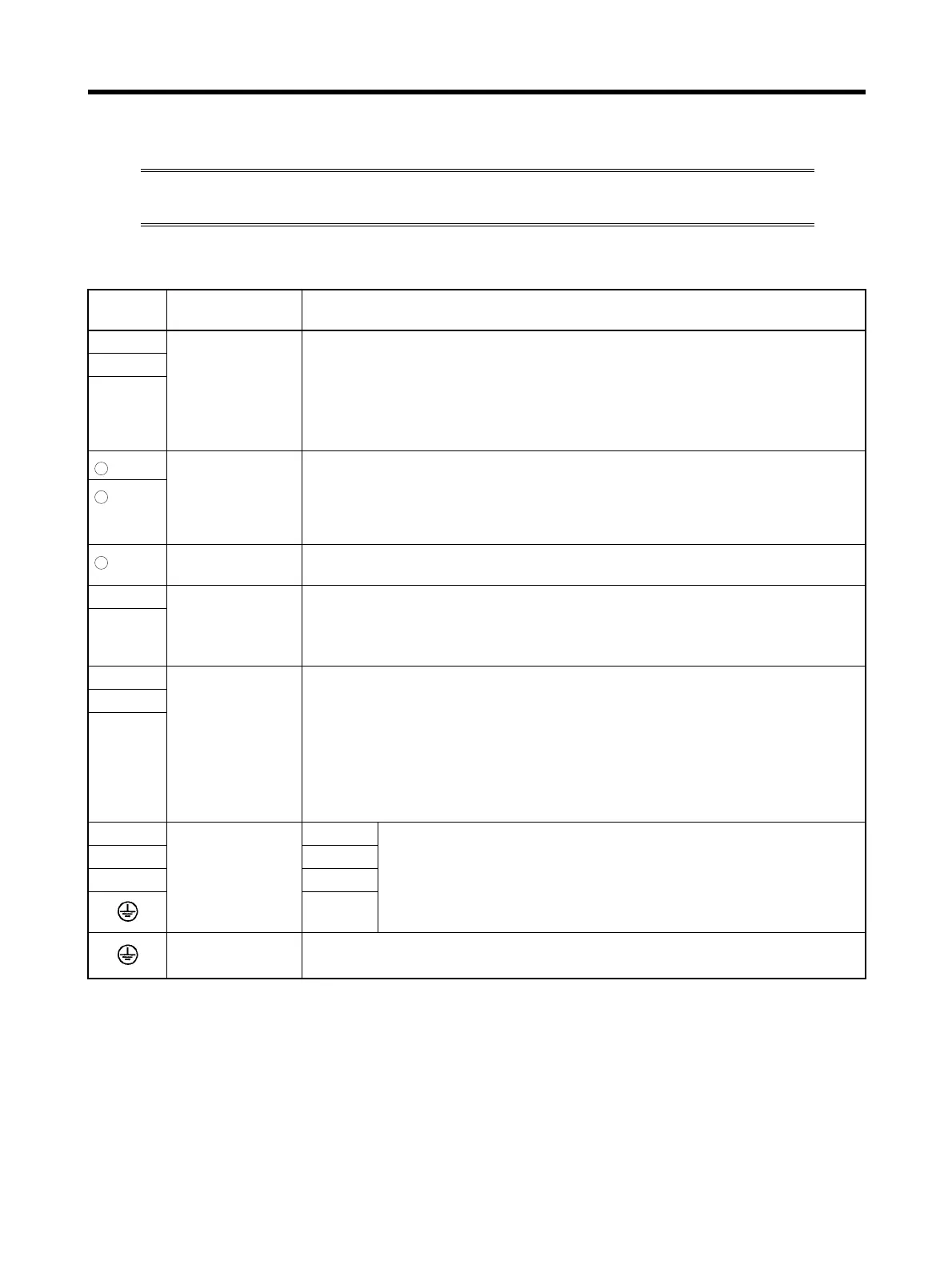
■ Terminal Block Names and Functions
Terminal
label
Name Function
L1 Main circuit
power supply
input
R7D-AP@H:
Single-phase 200/230 V AC (170 to 253 V), 50/60 Hz
R7D-AP@L:
Single-phase 100/115 V AC (85 to 127 V), 50/60 Hz
Note Only the R7D–AP08H (750 W) has an L3 terminal, enabling three-phase
input: Three-phase 200/230 V AC (170 to 253 V AC) 50/60 Hz
L2
L3
1
Connection ter-
minals for DC
Reactor for
power supply
harmonic control
Normally short between +1 and +2.
When harmonic control is required, connect a DC Reactor between +1 and +2.
2
Main circuit DC
output (negative)
Do not connect anything to this terminal.
L1C Control circuit
power supply
input
R7D-AP@H:
Single-phase 200/230 V AC (170 to 253 V), 50/60 Hz
R7D-AP@L:
Single-phase 100/115 V AC (85 to 127 V), 50/60 Hz
L2C
B1 External regener-
ation resistance
connection termi-
nals
30 to 200 W: An External Regeneration Resistor cannot be connected to these
terminals.
400 W: These terminals normally do not need to be connected. If there is high
regenerative energy, connect an External Regeneration Resistor between B1
and B2.
750 W: Normally shorted between B2 and B3. If there is high regenerative
energy, remove the short bar between B2 and B3 and connect an External
Regeneration Resistor between B1 and B2.
B2
B3
UServomotor con-
nection terminals
Red These are the output terminals to the Servomotor. Be careful to wire
them correctly.
VWhite
WBlue
Green/
Ye l l ow
Frame ground This is the ground terminal. Ground to a minimum of Class D ground
(Class 3 ground: 100
Ω or less).
+
+
−