EasyManua.ls Logo

Omron SYSMAC mini SP10 User Manual

Omron SYSMAC mini SP10
176 pages
To Next Page IconTo Next Page
To Previous Page IconTo Previous Page
Page #115 background imageLoading...
Page #115 background image
107
operand bits in the step are turned OFF and all timers in the step are reset to
their SVs. Counters, shift registers, and bits used in KEEP(12) maintain sta-
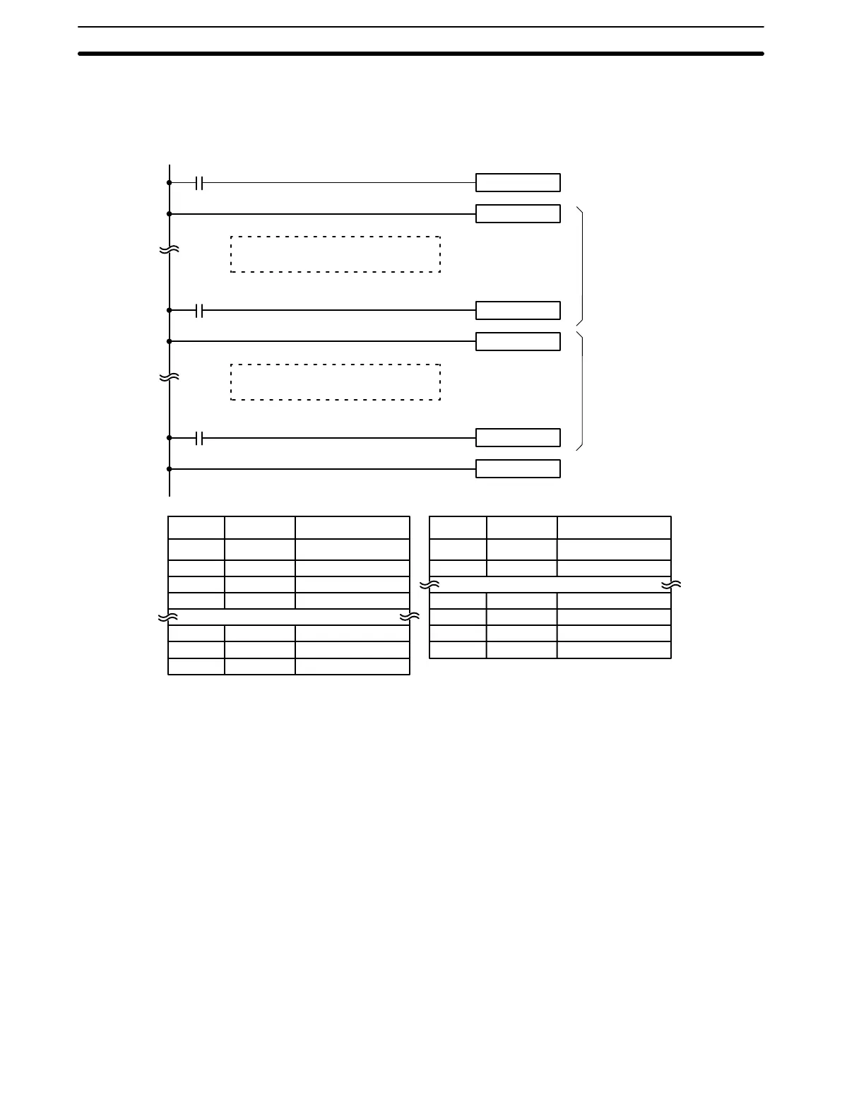
tus. Two simple steps are shown below.
SNXT(05) 0200
STEP(04) 0200
0000
Step controlled by 0200
SNXT(05) 0201
STEP(04) 0201
0001
Step controlled by 0201
SNXT(05) 0202
STEP(04)
0002
Starts step execution
Ends step execution
1st step
2nd step
Address Instruction Operands Address Instruction Operands
000 LD 0000
001 SNXT(05) 0200
002 STEP(04) 0200
Step controlled by 0200.
030 LD 0001
031 SNXT(05) 0201
032 STEP(04) 0201
Step controlled by 0201.
051 LD 0002
052 SNXT(05) 0202
053 STEP(04) ---
Steps can be programmed in consecutively. Each step must start with
STEP(04) and generally ends with SNXT(05). When steps are programmed
in series, three types of execution are possible: sequential, branching, or par-
allel. The execution conditions for, and the positioning of, SNXT(05) deter-
mine how the steps are executed.
Interlocks and END(01) cannot be used within step programs.
Bits used as control bits must not be used anywhere else in the program un-
less they are being used to control the operation of the step.
If output bits, work bits, or LR bits are used for control bits, their status will be
lost during any power interruption. If it is necessary to maintain status to re-
sume execution at the same step, DR bits must be used.
0411: Step Start Flag; turns ON for one scan when STEP(04) is executed
and can be used to reset counters in steps as shown below if neces-
sary.
Precautions
Flags
Instruction Set Section 3-7

Table of Contents

Question and Answer IconNeed help?

Do you have a question about the Omron SYSMAC mini SP10 and is the answer not in the manual?

Omron SYSMAC mini SP10 Specifications

General IconGeneral
ManufacturerOmron
SeriesSYSMAC mini
ModelSP10
Output TypeRelay
Number of Inputs6
Number of Outputs4
Communication PortRS-232C
TypePLC
Input Voltage100 to 240 VAC
Storage Temperature-25 to 65°C

Summary

PRECAUTIONS

1 Intended Audience

Manual intended for personnel familiar with electrical systems and FA systems.

2 General Precautions

User must operate product per specifications and consult OMRON for non-specified conditions.

3 Safety Precautions

Precautions against electrical shock and electrocution when handling PC.

4 Operating Environment Precautions

Conditions to avoid for proper PC operation, e.g., temperature, humidity.

5 Application Precautions

Precautions for electrical grounding, power supply, and installation.

SECTION 1 Introduction

1-1 Features

Overview of SP-series PCs' compact size, high-performance, and features.

1-2 PC Basics

Explanation of PC components, operation, and terminology.

1-3 Units

Description of CPU, Programming Console, and Link Adapter components.

1-4 PC Configuration

Details on basic and expanded system configurations using PCs and Link Adapters.

SECTION 2 Installation

2-1 Dimensions

Mounting dimensions for CPUs, Link Adapter, and Programming Console.

2-2 Installation

Information on installation environment, cooling, noise prevention, and mounting.

2-3 Wiring

Guidelines for power supply, I/O connections, and wiring precautions.

2-4 Programming Console

Procedures for connecting and designating the PC and input filters.

SECTION 3 Programming

3-1 Introduction

Overview of basic steps for writing, inputting, and debugging programs.

3-2 Memory Areas

Details on memory areas (Input, Output, Work, Dedicated, DR, LR, TC) and their structures.

3-3 The Programming Console

Explanation of Programming Console functions, keyboard, and modes.

3-4 Basic Programming

Core concepts of ladder diagram, terminology, mnemonic code, and basic instructions.

3-5 Inputting the Program

Step-by-step guide for program input, editing, checking, and transfer.

3-6 Advanced Programming

Techniques for interlocks, bit control, differentiated instructions, and work bits.

3-7 Instruction Set

Detailed explanation of all SP-series PC instructions, formats, and execution times.

SECTION 3 Debugging

3-8-1 Displaying and Clearing Error Messages

Procedure to identify, display, and clear error messages using the console.

3-8-2 Reading the Scan Time

Operation to read present and maximum scan times (SP16/SP20 only).

SECTION 3 Program Execution

3-9-1 Scan

Explanation of the CPU scan cycle and its impact on program timing.

3-10 I/O Response Time

Explanation of I/O response time calculation for single PCs and multiple PCs.

SECTION 4 Operation

4-1 Monitoring Operation and Modifying Data

Procedures for monitoring bits, words, timers, counters, and modifying data.

4-2 Memory Card Initialization

Steps to initialize Memory Cards for program backup.

Appendix A Standard Models

Appendix B Specifications

General Ratings

Technical specifications for SP-series PCs, including general ratings.

Input Specifications

Detailed specifications for PC input voltage, impedance, current, and delays.

Output Specifications

Detailed specifications for PC output switching capacity, delays, and life.

CPU Characteristics

Specifications regarding PC control method, I/O control, instruction length, and speed.

Appendix C Programming Instructions and Execution Times

Basic Instructions

Reference for basic ladder diagram instructions, symbols, key inputs, and operands.

Special Instructions

Reference for special instructions like END, Interlocks, STEP, and timers/counters.

Instruction Execution Times

Table detailing instruction execution times based on conditions and operands.

Appendix D Programming Console Operations

Appendix E Error and Arithmetic Flag Operation

Appendix F I/O Assignment Sheets

I/O Bits

Templates for recording I/O bit allocations and terminal assignments for Units.

TC Area and Work Bits

Templates for recording TC area and work bit usage and notes.

Appendix G Program Coding Sheet

Glossary

Index

Revision History

Related product manuals