86
0000
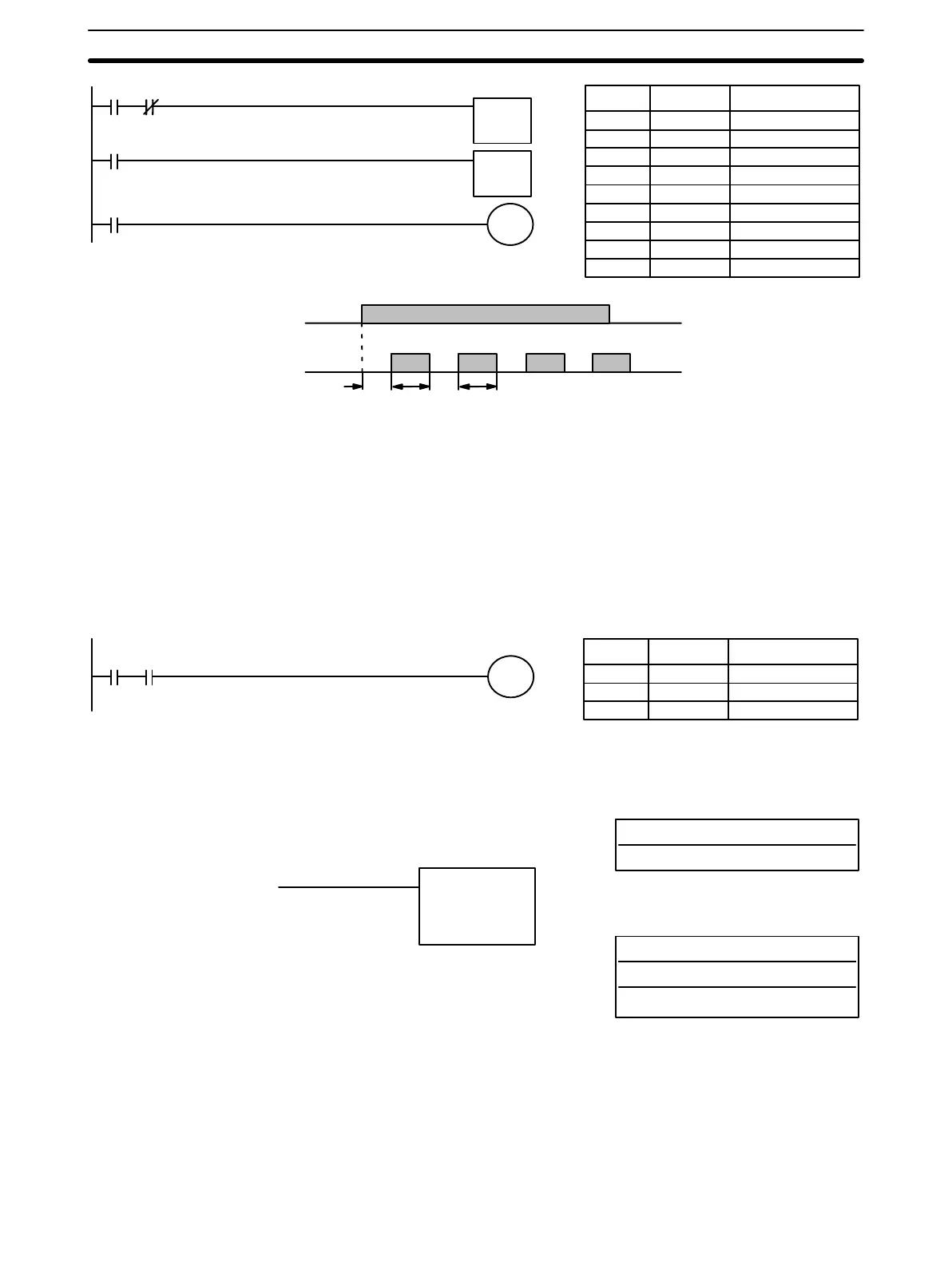
TIM 01
TIM 01
0103
0000
0103
1.5 s1.0 s 1.5 s1.0 s
Address Instruction Operands
000 LD 0000
001 AND NOT TIM 02
002 TIM 01
# 0010
003 LD TIM 01
004 TIM 02
# 0015
005 LD TIM 01
006 OUT 0103
TIM 02
#0015
TIM 01
#0010
1.0 s
1.5 s
TIM 02
A simpler but less flexible method of creating a flicker bit is to AND one of the
dedicated clock pulse bits with the execution condition that is to be ON when
the flicker bit is operating. Although this method does not use TIM, it is in-
cluded here for comparison. This method is more limited because the ON
and OFF times must be the same and they depend on the clock pulse bits
available.
In the following example the 1-second clock pulse is used (0308) so that
0101 would be turned ON and OFF every second, i.e., it would be ON for 0.5
seconds and OFF for 0.5 seconds. Precise timing and the initial status of
0101 would depend on the status of the clock pulse when 0000 goes ON.
0000 0308
0101
Address Instruction Operands
000 LD 0000
001 AND 0308
002 OUT 0101
3-7-15 TIMER - TIMM(20)
N: TC number
# (00 through 15)
Ladder Symbol
Definer Values
SV: Set value (BCD)
SP10: #
SP16, SP20: I/O, work, DR, LR, #
Operand Data Areas
TIMM(20) N
SV
SV is between 00.00 and 99.99 seconds. The decimal point is not entered.
Each TC number can be used as the definer in only one timer or counter in-
struction.
TC 11 through TC 15 should not be used in TIMM(20) if they are required for
the specific instruction to which they are assigned. Refer to the table on page
82.
Limitations
Instruction Set Section 3-7