113
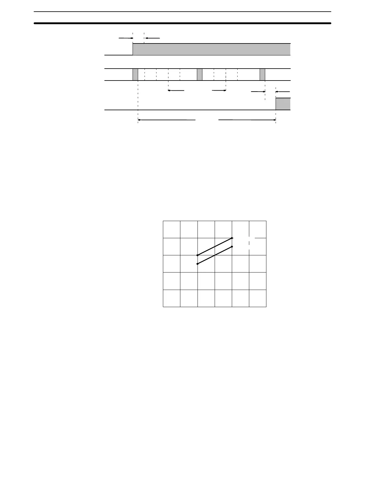
Execu-
tion
input delay
IN
OUT
PC Process
Scan time
output
delay
T
max
ACDE ABCD E B DC
T
max
= Maximum I/O response time
= input delay + filter time + (scan time x 2) + output delay
= C + (B + 0.5 ms) + ((300 µs + program execution time) x 2) + A
3-10-2 Multiple PCs
If more than one PC is linked via a Link Adapter in a distributed control sys-
tem, the I/O response time is increased with every PC having their own re-
sponse time. The average I/O response time given as a function of the num-
ber of linked PCs is shown in the following graph. For a system of four PCs,
the maximum I/O response time is 0.4 s.
0.4
0.3
0.2
0.1
1 234
Average I/O
response time
(s)
128 pts.
64 pts.
No. of linked PCs
Note The duration required to process linked PCs is increased if a PC already
linked is disconnected from the network.
I/O Response Time Section 3-10