50
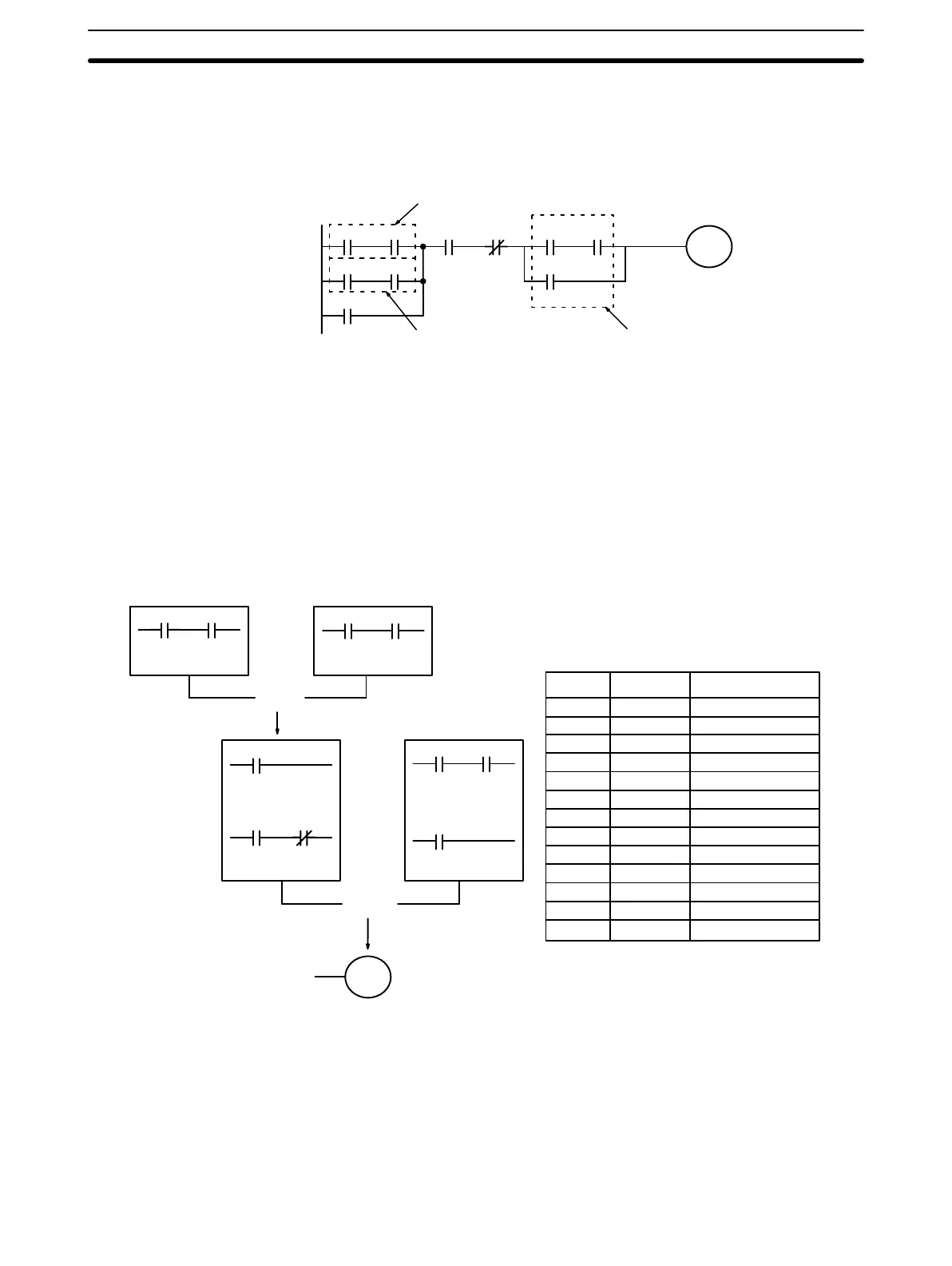
The next and final example may at first appear very complicated but can be
coded using only two logic block instructions. The diagram appears as fol-
lows:
0000 0001
0100
0002 0003
0010 0011
0004 0005
0100
0106
Block cBlock b
Block a
The first logic block instruction is used to combine the execution conditions
resulting from blocks a and b, and the second one is to combine the execu-
tion condition of block c with the execution condition resulting from the nor-
mally closed condition assigned bit 0003. The rest of the diagram can be
coded with OR, AND, and AND NOT instructions. The logical flow for this
and the resulting code are shown below.
0000 0001
0100
0002 0003
0010 0011
0004 0005
0100
0106
Block c
Block bBlock a
OR LD
LD 0000
AND 0001
OR 0100
AND 0002
AND NOT 0003
LD 0010
AND 0011
LD 0106
LD 0004
AND 0005
AND LD
Address Instruction Operands
000 LD 0000
001 AND 0001
002 LD 0010
003 AND 0011
004 OR LD --
005 OR 0100
006 AND 0002
007 AND NOT 0003
008 LD 0004
009 AND 0005
010 OR 0106
011 AND LD --
012 OUT 0100
3-4-7 Coding Multiple Right-hand Instructions
If there is more than one right-hand instruction executed with the same ex-
ecution condition, they are coded consecutively following the last condition
Basic Programming Section 3-4