85
0000
0100 0000
TIM 01
TIM 02
0000
0100
5.0 s
3.0 s
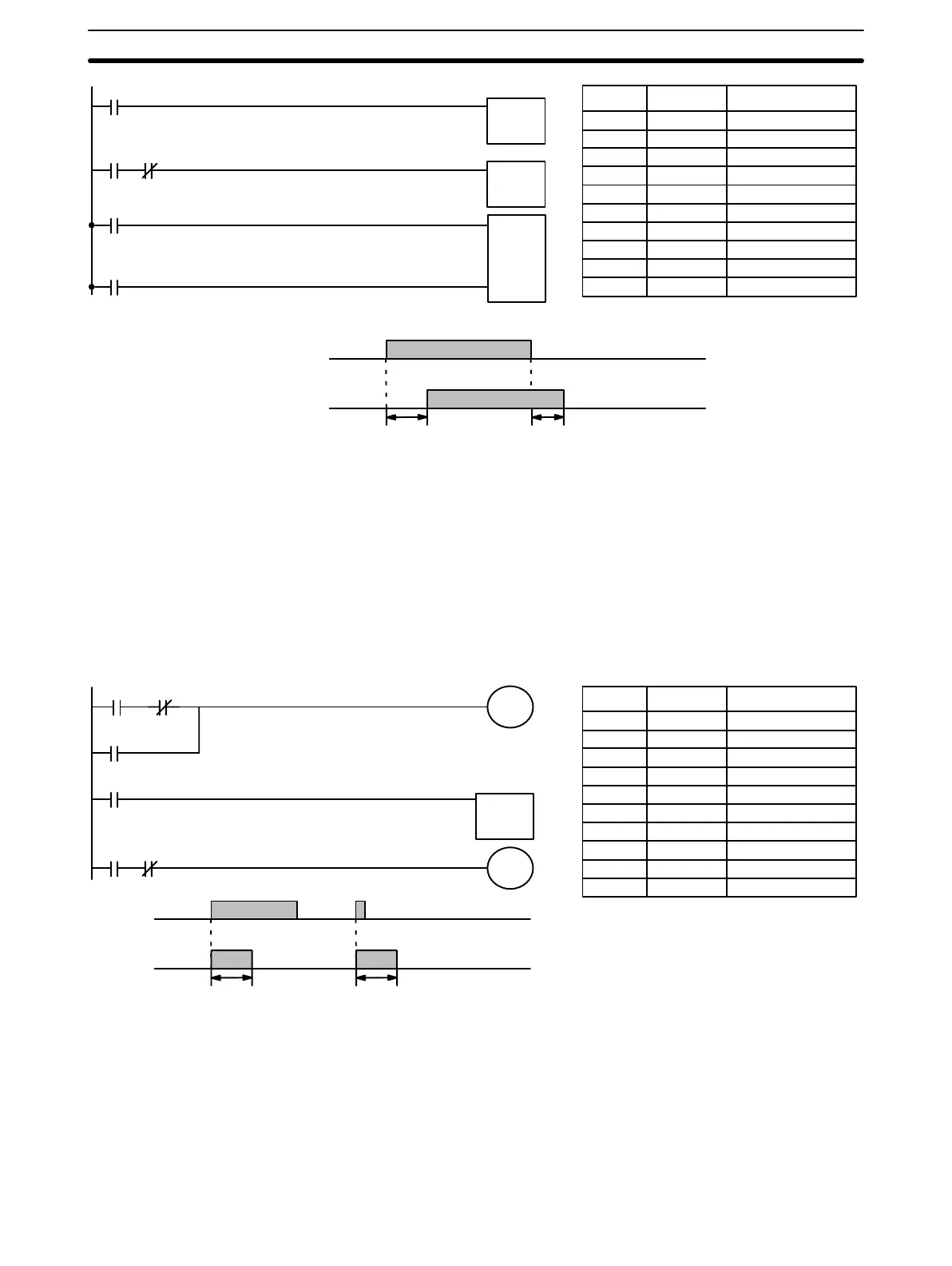
Address Instruction Operands
000 LD 0000
001 TIM 01
# 0050
002 LD 0100
003 AND NOT 0000
004 TIM 02
# 0030
005 LD TIM 01
006 LD TIM 02
007 KEEP(12) 0100
TIM 01
#0050
TIM 02
#0030
S
R
KEEP(12)
0100
5.0 s
3.0 s
The length of time that a bit is kept ON or OFF can be controlled by combin-
ing TIM with OUT or OUT NOT. The following diagram demonstrates how
this is possible. In this example, bit 0103 would remain ON for 1.5 seconds
after 0000 goes ON regardless of the time 0000 stays ON. This is achieved
by using 0215 as a self-maintaining bit activated by 0000 and turning ON
0103 through it. When TIM 01 comes ON (i.e., when the SV of TIM 01 has
expired), 0103 will be turned OFF through TIM 01 (i.e., TIM 01 will turn ON
and because it is programmed as a normally closed condition, an OFF ex-
ecution condition will be created for OUT 0103).
0000
TIM 01
0215
0215
0215 TIM 01
0215
0103
0000
0103
1.5 s
1.5 s
Address Instruction Operands
000 LD 0215
001 AND NOT TIM 01
002 OR 0000
003 OUT 0215
004 LD 0215
005 TIM 01
# 0015
006 LD 0215
007 AND NOT TIM 01
008 OUT 0103
TIM 01
#0015
1.5 s
Bits can be programmed to turn ON and OFF at regular intervals while a des-
ignated execution condition is ON by using TIM twice. One TIM functions to
turn ON and OFF a specified bit, i.e., the Completion Flag of this TIM turns
the specified bit ON and OFF. The other TIM functions to control the opera-
tion of the first TIM, i.e., when the first TIM’s Completion Flag goes ON, the
second TIM is started and when the second TIM’s Completion Flag goes ON,
the first TIM is started.
Example 4:
One-Shot Bits
Example 5:
Flicker Bits
Instruction Set Section 3-7