BASIC commands
PROGRAMMING MANUAL 55
Revision 1.0
/i
/i
• SHAPE BLOCK: This is directly pointed to by the CAMBOX command as
in any CAMBOX.
• CONTROL BLOCK: This is pointed to by the third CAMBOX parameter
in this options mode only. It is of fixed length (7 table values). It is impor-
tant to note that the control block is modified during the CAMBOX opera-
tion. It must therefore be re-initialised prior to each use.
• PATTERN BLOCK: The start and end of this are pointed to by 2 of the
CONTROL BLOCK values. The pattern sequence is a sequence of scale
factors for the SHAPE.
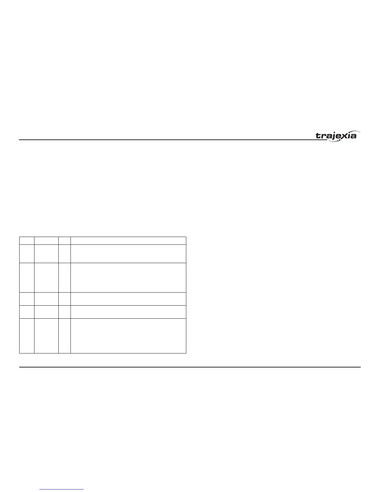
The table below gives the CONTROL BLOCK parameters
Note: READ/WRITE values can be written to by the user program during the
pattern CAMBOX execution.
Value Parameter R/W Description
0 CURRENT
POSITION
R The current position within the TABLE of the pattern sequence.
This value should be initialised to the START PATTERN
number.
1FORCE
POSITION
R/W Normally this value is -1. If at the end of a SHAPE the user
program has written a value into this TABLE position the pat-
tern will continue at this position. The system software will then
write -1 into this position. The value written must be inside the
pattern such that the value: CB(2)<=CB(1)<=CB(3)
2START
PATTERN
R The position in the TABLE of the first pattern value.
3END
PATTERN
R The position in the TABLE of the final pattern value.
4 REPEAT
POSITION
R/W The current pattern repeat number. Initialise this number to 0.
The number will increment when the pattern repeats if the link
axis motion is in a positive direction. The number will decre-
ment when the pattern repeats if the link axis motion is in a
negative direction. Note that the counter runs starting at zero:
0,1,2,3...