ENGLISH
3 Electrical Installation
I67E-EN V1000 Quick Start Guide 9
3 Electrical Installation
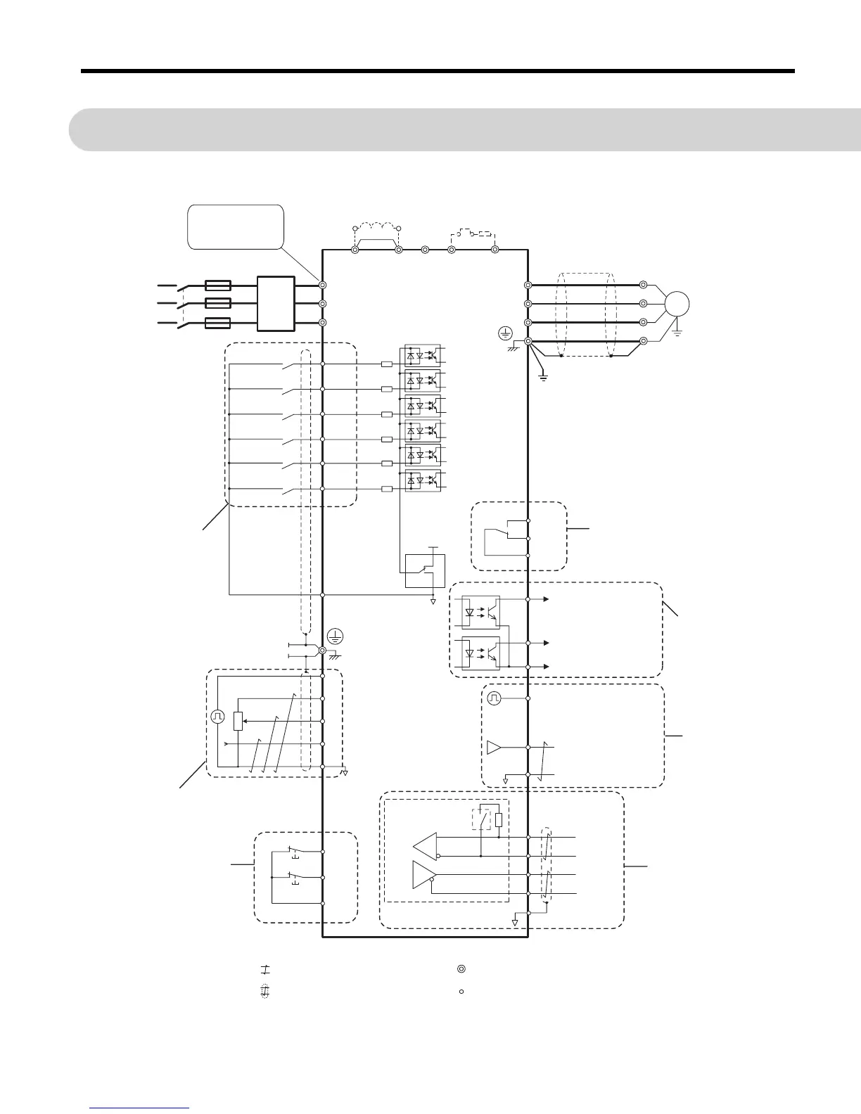
The figure below shows the main and control circuit wiring.
Power
Supply
R/L1
S/L2
T/L3
S1
S2
S3
S4
S5
S6
㪄
B1+1+2 B2
L1
L2
L3
U/T1
V/T2
W/T3
24 V
0V
SINK
SOURCE
MA
P1
MB
MC
+24 V 8 mA
M
U
V
W
SC
P2
MP
AM
AC
PC
IG
R+
R−
S+
S−
H2
RP
+V
A1
A2
AC
2 kΩ
HC
H1
DC reactor
(option)
For 1-phase
power supply use
R/L1 and S/L2
Filter
Fuses
Main
Switch
Forward/Stop
Reverse/Stop
External Fault
Fault Reset
Multi-speed 1
Multi-speed 2
Multi-function
digital inputs
(default setting)
Link
Thermal
relay
Braking
resistor
(opt)
V1000
Ground
Multi-function relay output
250 Vac / 30 Vdc (10 mA to 1A)
(default setting)
Fault
During run
Frequency agree
Photocoupler
common
Multi-function photo-
coupler output
48 Vdc, max. 50 mA
(default setting)
DIP
switch S3
Shielded ground
terminal
Pulse Input
(max. 32kHz)
Multi-function analog input 1
0 to 10 V (20 k
Ω
)
Multi-function analog input 2
0 to 10 V (20 k
Ω
) or
0/4 to 20 mA (250
Ω
)
Analog input power supply
+10.5 Vdc, max. 20 mA
Multi- function pulse / analog inputs
(default: frequency reference)
Safe Disable
inputs
Monitor outputs
(default setting)
Analog output
0 to +10 Vdc (2mA)
(Output frequency)
Pulse train output
(max. 32 kHz)
(Output frequency)
Terminal resistance
(120
Ω
, 1/2 W)
Memobus comm.
RS-485/422
max. 115 kBps
Shielded
Cable
Symbols:
Use twisted pair cables
Use shielded twisted pair cables
Indicates a main circuit terminal
Indicates a control circuit terminal.

 Loading...


