3 Electrical Installation
I67E-EN V1000 Quick Start Guide 13
ENGLISH
• For external control power supply use a UL Listed Class 2 power supply.
• Use twisted-pair or shielded twisted-pair cables for control circuits to prevent operating
faults.
• Ground the cable shields with the maximum contact area of the shield and ground.
• Cable shields should be grounded on both cable ends.
Main Circuit Terminals
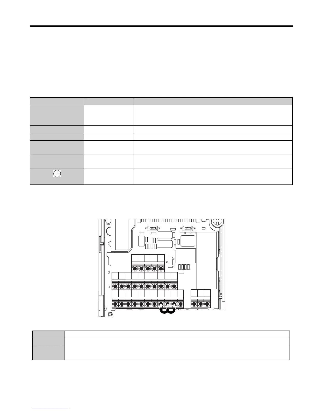
Main Circuit Terminals
The figure below shows the control circuit terminal arrangement. The drive is equipped with
screwless terminals
There are three DIP switches, S1 to S3, located on the terminal board
Terminal Type Function
R/L1, S/L2, T/L3
Main circuit power
supply input
Connects line power to the drive.
Drives with single-phase 200 V input power use terminals R/L1 and S/
L2 only (T/L3 is not used).
U/T1, V/T2, W/T3 Drive output Connects to the motor.
B1, B2 Braking resistor For connecting a braking resistor or the braking resistor unit option.
+1, +2
DC reactor connec-
tion
Linked at shipment. Remove the link to install a DC choke.
+1, –
DC power supply
input
For connecting a DC power supply.
(2 terminals)
Ground Terminal
For 200 V class: Ground with 100 Ω or less
For 400 V class: Ground with 10 Ω or less
SW1 Switches analog input A2 between voltage and current input
SW2 Enables or disables the internal RS422/485 comm. port terminal resistance.
SW3
Used to select sourcing (PNP)/sinking (NPN, default) mode for the digital inputs (PNP requires
external 24 Vdc power supply)
S1 S2 S3 S4 S5 S6 SC HC H1 H2 RP
R+ R- S+ S- IG
P1 P2 PC A1 A2 +V AC AM AC MP
MA MB MC
S2 S1
S3

 Loading...


