3 Electrical Installation
14 I67E-EN V1000 Quick Start Guide
Control Circuit Terminals
NOTICE! The terminals HC, H1, H2 are used for the Safe Disable function which
cuts the output voltage in less than 1 ms if at least one of the inputs H1 or
H2 is opened. It is designed in accordance with the EN954-1, safety
category 3 and EN61508, SIL2. It and can be utilized to perform a safe
stop as defined by the EN60204-1, stop category 0. Do not remove the
wire link between HC, H1, or H2 unless the Safe Disable function is used.
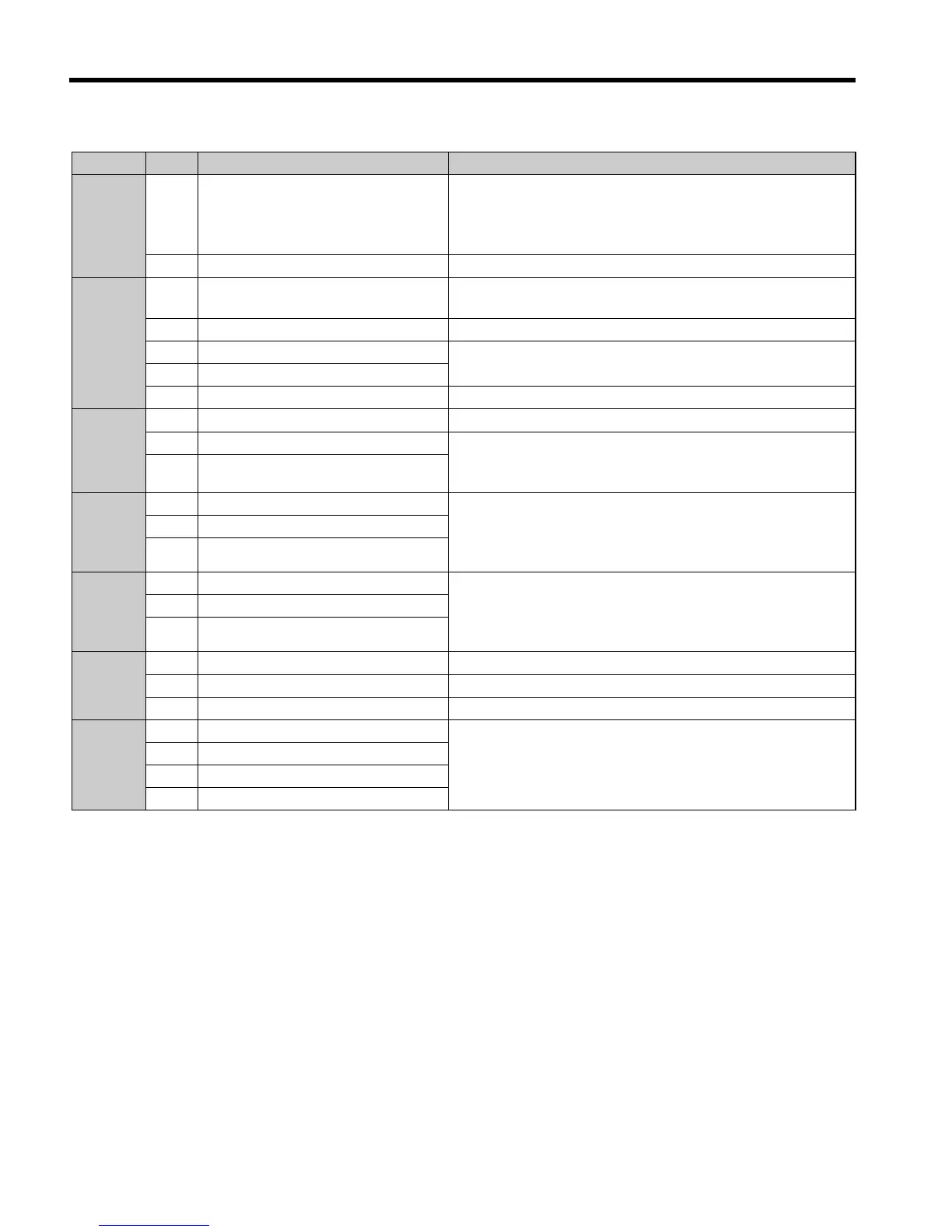
Type No. Terminal Name (Signal) Function (Signal Level), Default Setting
Multi-
Function
Digital
Inputs
S1
to
S6
Multi-function digital input 1 to 6
Photocoupler inputs, 24 Vdc, 8 mA
Note: Drive preset to sinking mode (NPN). When using
source mode, set DIP switch S3 to “SOURCE” and use an
external 24 Vdc (±10%) power supply.
SC Multi-function input common Sequence common
Multi-
Function
Analog/
Pulse
Inputs
RP Pulse train input
Response frequency: 0.5 to 32 kHz, Duty: 30 to 70%, High:
3.5 to 13.2 V, Low: 0.0 to 0.8 V, input impedance: 3 kΩ)
+V Analog input power supply +10.5 V (max allowable current 20 mA)
A1 Multi-function analog input 1
0 to +10 Vdc (20 kΩ) resolution 1/1000
0/4 to 20 mA (250 Ω) resolution: 1/500 (A2 only)
A2 Multi-function analog input 2
AC Frequency reference common 0 V
Safe
Disable
Inputs
HC Safe Disable Input common +24 V (max 10 mA allowed)
H1 Safe Disable Input 1 One or both open: Drive output disabled (time from input
open to drive output switch off is less than 1 ms)
Both Closed: Normal operation
H2 Safe Disable Input 2
Multi-
Function
Relay
Output
MA N.O. (fault)
Digital relay output
30 Vdc, 10 mA to 1 A
250 Vac, 10 mA to 1 A
MB N.C. output (fault)
MC Digital output common
Multi-
Function
PHC
Output
P1 Photocoupler output 1
Digital photocoupler output
48 Vdc, 0 to 50 mA
P2 Photocoupler output 2
PC Photocoupler output common
Monitor
Output
MP Pulse train output 32 kHz (max)
AM Analog monitor output 0 to 10 Vdc (2 mA or less), Resolution: 1/1000 (10 Bit)
AC Monitor common 0 V
MEMO-
BUS/
Commu-
nication
R+ Communications input (+)
MEMOBUS/Modbus communication.:
RS-485 or RS-422, 115.2 kBps (max)
R– Communications input (–)
S+ Communications output (+)
S- Communications output (–)

 Loading...


