3 Electrical Installation
I67E-EN V1000 Quick Start Guide 11
ENGLISH
Control Circuit
The control terminal board is equipped with screwless terminals. Always use wires within
the specification listed below. For safe wiring it is recommended to use solid wires or flexi-
ble wires with ferrules. The stripping length respectively ferrule length should be 8 mm.
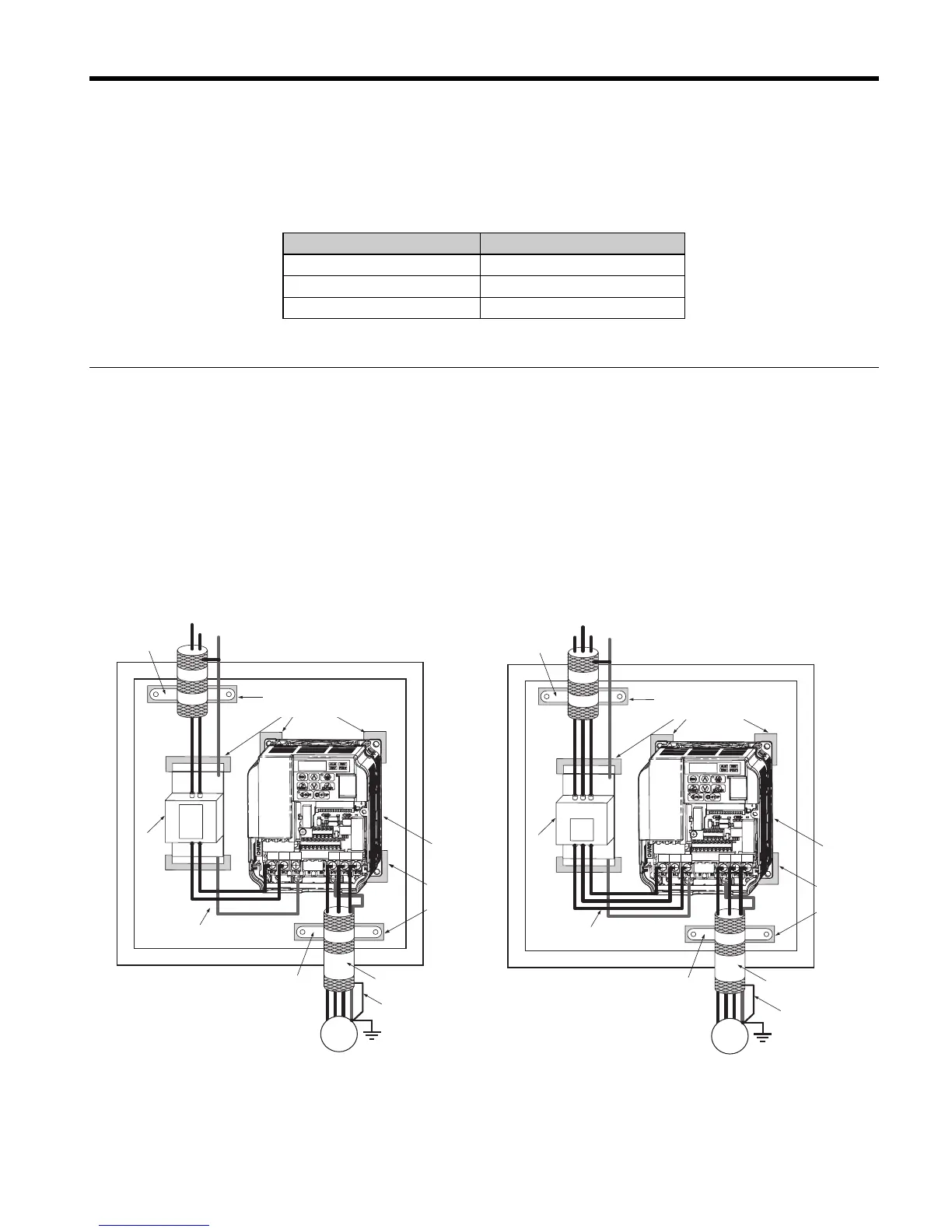
EMC Filter Installation
This drive has been tested in accordance with European standards EN61800-3. In order to
comply to the EMC standards, wire the main circuit as described below.
1. Install an appropriate EMC noise filter to the input side.See the list above or refer to the
instruction manual for details.
2. Place the drive and EMC noise filter in the same enclosure.
3. Use braided shield cable for the drive and motor wiring
4. Remove any paint or dirt from ground connections for minimal ground impedance
5. Install an AC reactor at drives smaller than 1 kW for compliance with the
EN61000-3-2. Refer to the instruction manual or contact your supplier for details
EMC Standards Compliant Wiring of Single- and Three Phase Units
Wire Type Wire size
Solid 0.2 to 1.5 mm²
Flexible 0.2 to 1.0 mm²
Flexible with ferrule 0.25 to 0.5 mm²
N
L1
E
N
L1
PE
R/L1 S/L2 T/L3
U/T1 V/T2
W/T3
Wiring distance as
short as possible
Cable shield
grounding clamp
Drive
Cable clamp
Braid shielded motor
cable
EMC
Filter
Grounding Surface
(remove any paint)
Metal plate
Panel or mounting wall
M
Grounding
Surface
(remove any
paint)
Ground shield at
motor side
L3
L2
L1
R/L1 S/L2 T/L3
U/T1 V/T2
W/T3
E
L1
PE
R/L1 S/L2 T/L3
U/T1 V/T2
W/T3
Wiring distance as
short as possible
Cable shield
grounding clamp
Drive
Cable clamp
Braid shielded motor
cable
EMC
Filter
Grounding Surface
(remove any paint)
Metal plate
Panel or mounting wall
M
Grounding
Surface
(remove any
paint)
Ground shield at
motor side
L3
L2

 Loading...


