6 Parameter Table
I67E-EN V1000 Quick Start Guide 23
ENGLISH
Par. Name Description
C1-03
to
C1-08
Accel/Decel
Times 2 to 4
Set the accel/ decel times 2 to 4 (set
like C1-01/02)
C2-01 S-Curve 1 S-curve at acceleration start.
C2-02 S-Curve 2 S-curve at acceleration end.
C2-03 S-Curve 3 S-curve at deceleration start.
C2-04 S-Curve 4 S-curve at deceleration end.
Slip Compensation
C3-01
Slip Com-
pensation
Gain
• Increase if the speed is lower than
the frequency reference
• Decrease if the speed is higher
than the frequency reference.
C3-02
Slip Com-
pensation
Delay Time
• Decrease the setting when the slip
compensation is too slow.
• Increase the setting when the
speed is not stable.
Torque Compensation
C4-01
Torque
Compensa-
tion Gain
• Increase this setting when the
torque response is slow
• Decrease this setting when speed/
torque oscillations occur.
C4-02
Torque
Compensa-
tion Delay
Time
• Increase this setting when speed /
torque oscillations occur.
• Decrease the setting when the
torque response is too slow.
Duty Mode and Carrier Frequency
C6-01
Normal/
Heavy Duty
Selection
0: Heavy Duty (HD)
Constant torque applications
1:Normal Duty (ND)
Variable torque application
C6-02
Carrier Fre-
quency
Selection
1:2.0 kHz
2:5.0 kHz
3:8.0 kHz
4:10.0 kHz
5:12.5 kHz
6:15.0 kHz
7 to A: Swing PWM1 to 4
F: User defined
Frequency References
d1-01
to
d1-16
Frequency
Reference
1 to 16
Set the multi-speed references 1 to
16
d1-17 Jog Speed Jog speed
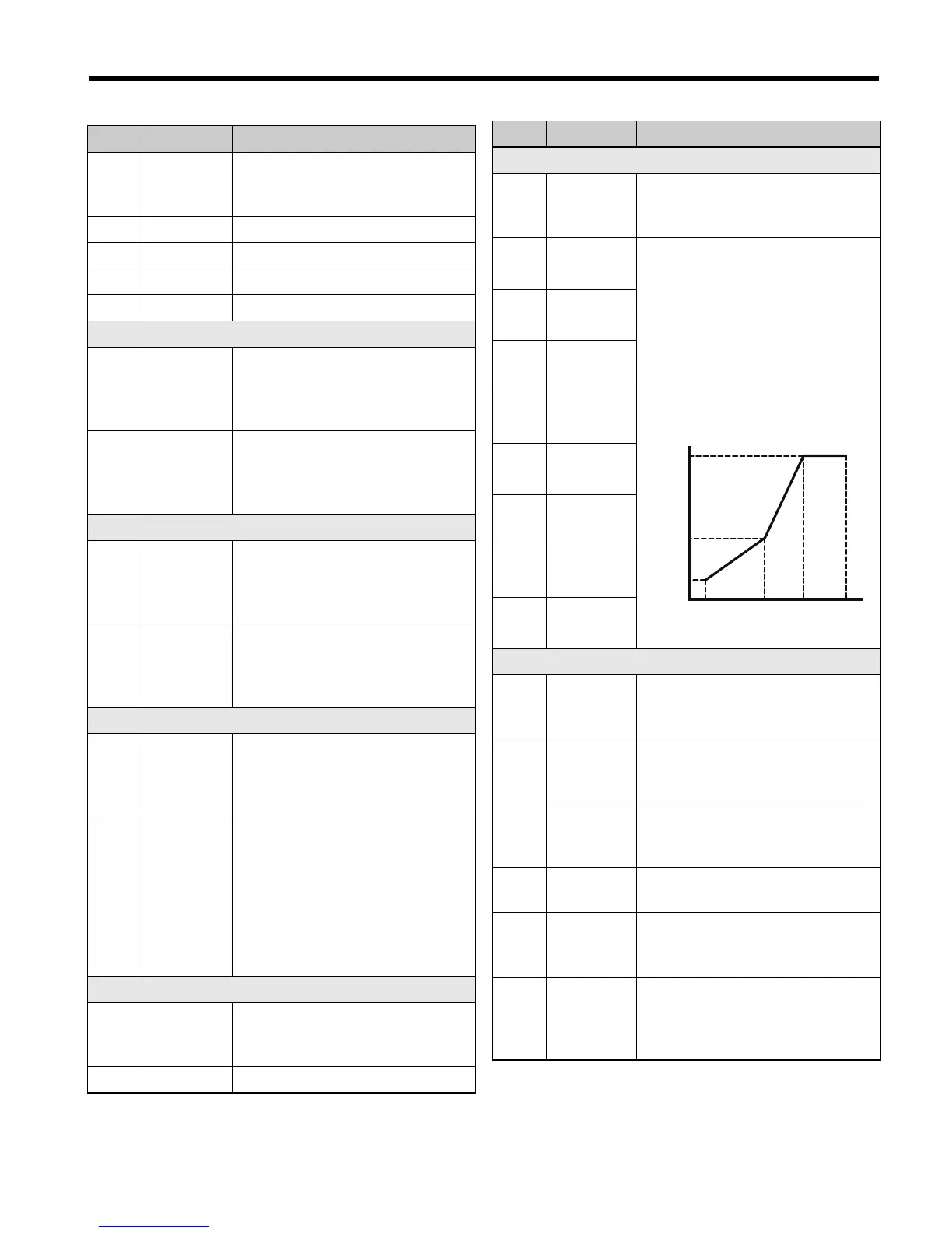
V/f Pattern
E1-01
Input
Voltage Set-
ting
Input Voltage
E1-04
Max. Out-
put Freq.
For a linear V/f characteristics, set
the same values for E1-07 and E1-
09. In this case, the setting for E1-
08 will be disregarded.
Ensure that the four frequencies are
set according to these rules or
OPE10 fault will occur:
E1-04 ≥ E1-06 ≥ E1-07 ≥ E1-09
E1-05
Max. Out-
put Voltage
E1-06
Base Fre-
quency
E1-07
Middle Out-
put Freq.
E1-08
Mid. Out-
put Voltage
E1-09
Min. Out-
put Freq.
E1-10
Min. Out-
put Voltage
E1-13
Base
Voltage
Motor Data
E2-01
Motor
Rated
Current
Automatically set during
Auto-Tuning.
E2-02
Motor
Rated Slip
Motor rated slip in hertz (Hz).
Automatically set by Rotational
Auto-Tuning.
E2-03
Motor
No-Load
Current
Magnetizing current in Ampere.
Automatically set by Rotational
Auto-Tuning.
E2-04 Motor Poles
Number of motor poles.
Automatically set by Auto-Tuning.
E2-05
Motor Line-
to-Line
Resistance
Sets the phase-to-phase motor
resistance in ohms.
Automatically set by Auto-Tuning.
E2-06
Motor
Leakage
Inductance
Sets the voltage drop due to motor
leakage inductance as a percentage
of motor rated voltage.
Automatically set by Auto-Tuning.
Par. Name Description
(E1-04)(E1-06)(E1-07)(E1-09)
(E1-10)
(E1-08)
(E1-05)
(E1-13)
Output voltage
Output frequency

 Loading...


