1-3SectionOperation
5
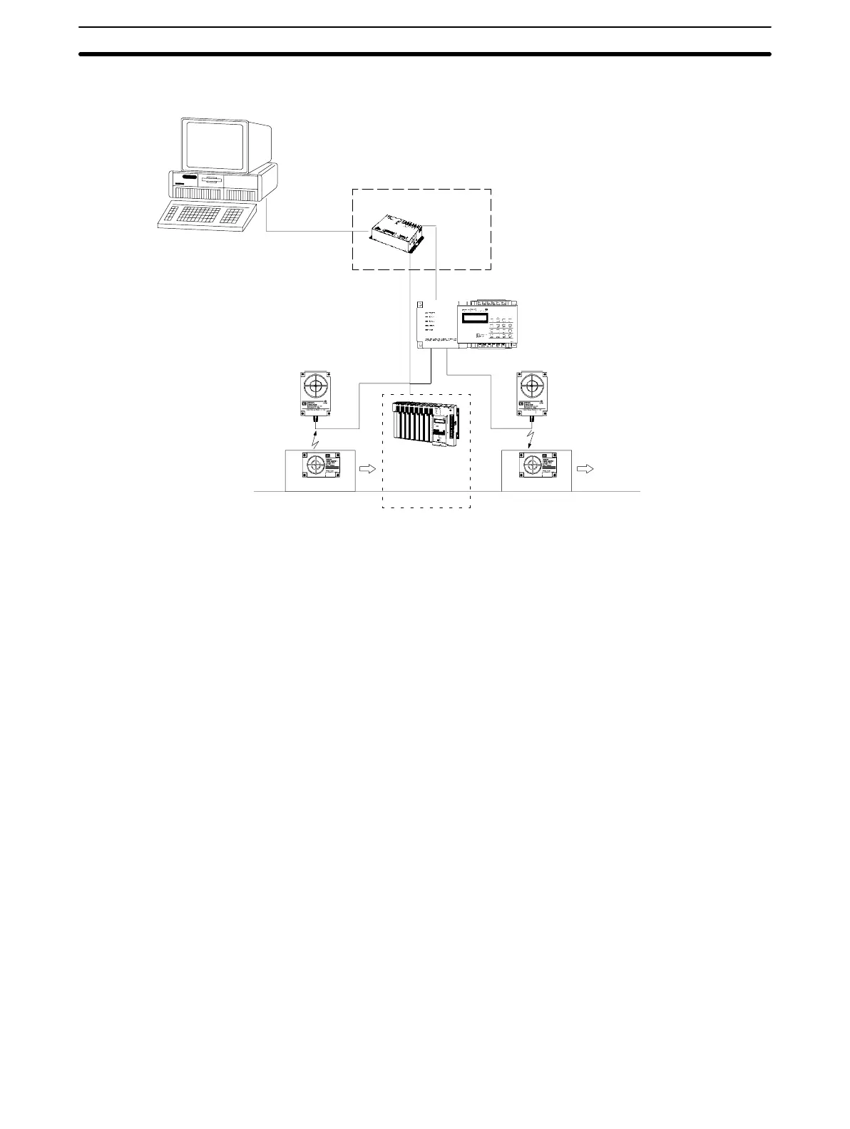
1-3 Operation
Link
Adaptor*
Machining/inspection
(Machining command data read)
To next process
R/W Head 2
ID Controller
(V600-CA2A-Vj)
RS-422
RS-232C
Host computer
Programmable
Controller
(PC)
R/W Head 1
PalletPallet
(W
rite inspection results data)
*When using a V600-CA2A-V
j
ID Controller
,
Link Adaptors must be used.
(IBM PC/A
T or compatible)
1, 2, 3...
1. When
a command is sent from the host computer to the ID Controller
, R/W
Head 1 enters the waiting condition and waits for the arrival of
the DC. The
command
data at this time specifies the memory area from which data is to
be read by R/W Head 1.
2. When
the DC arrives within communications range of R/W Head 1, the data
(format
and machining/inspection command data)
in the memory area indi
-
cated
by the read command is sent to the host computer as the response.
3. Based on the response data, the host computer transmits the workpiece
machining/inspection command to the PC.
4. Once operations in the machining/inspection process have been com-
pleted, machining/inspection results data is sent from the PC to the IBM
PC/AT or compatible.
5. The host computer sends a write command to the ID Controller, and this
time
R/W Head 2 waits for arrival of
the DC. This command sets the memory
area
to which R/W Head 2 is to write data and set the machining/inspection
results data.
6. When
the
DC arrives in the R/W Head 2 communications range, the machin
-
ing/inspection results data is written to the memory area specified by the
DC.

 Loading...


