1-2SectionSystem Configuration
4
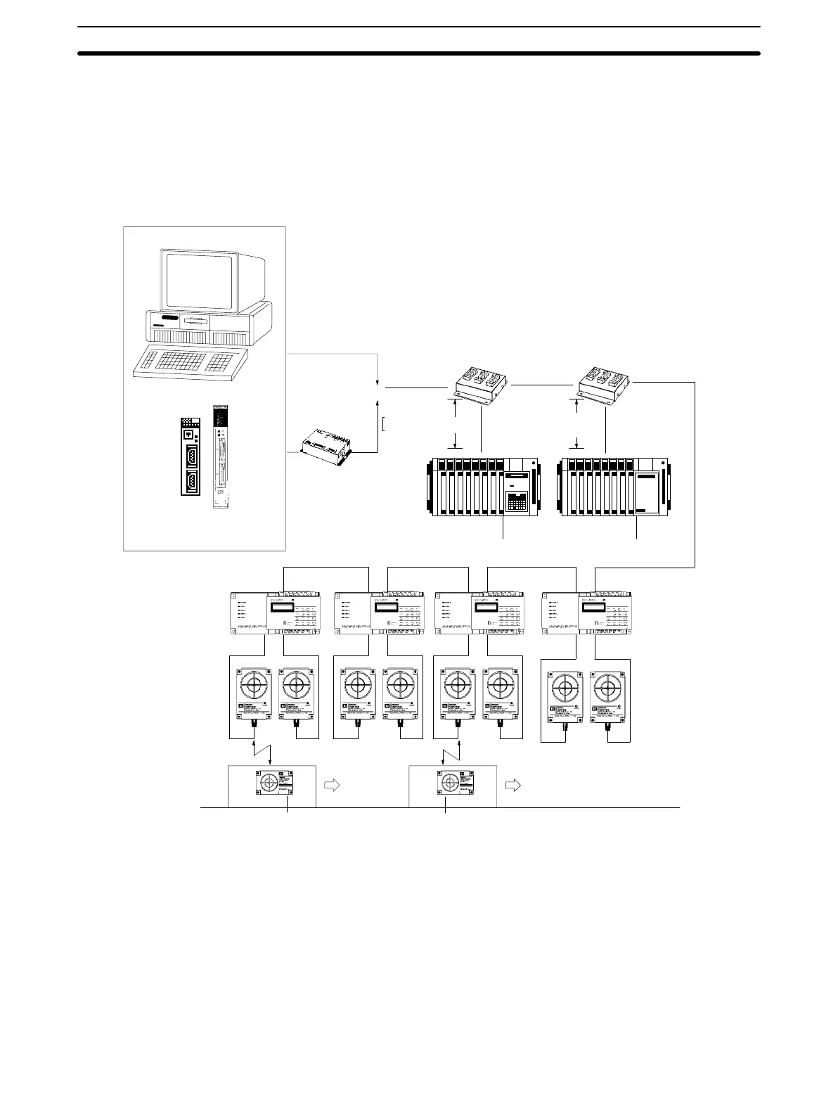
1-2-1 System Configuration for 1 to N Connection
This
system configuration is available only with the V600-CA2A-V
j
. Up to 16 ID
Controllers can be connected using the 1 to N configuration.
or
Unit 15 Unit 2 Unit 1 unit 0
Host computer
RS-422
RS-232C
(Termination
resistor ON)
B500-AL004(-P)
RS-422 Link Adaptor
RS-422
RS-422
RS-422 (branch line)
10m max
B500-AL001
RS-422
Link Adaptor
B500-AL001
RS-422
Link Adaptor
C500-LK201-V1
Host Link Unit
C120-LK202-V1
Host Link Unit
Pallet, etc.
Data carrier
V600-CA2A-Vj
ID Controller
Read/Write Head
(RT)=OFF
RS-422
(branch line)
10m max
C200H-ASC02 or
C500-ASC04 ASCII Unit
Note 1. Use communications cables with a maximum total length of 500 m.
2. Attach
B500-AL004(-P) Link Adaptors to both ends of the communications
cable and turn on the ID Controller termination resistor. Turn off the inter-
mediate ID Controller and the Host Link Unit.
3. When using a host computer with a built-in RS-422 interface, turn on only
the termination resistor of the terminal ID Controller.

 Loading...


