2-1SectionV600-CAjA-Vj ID Controller
8
2-1 V600-CAjA-Vj ID Controller
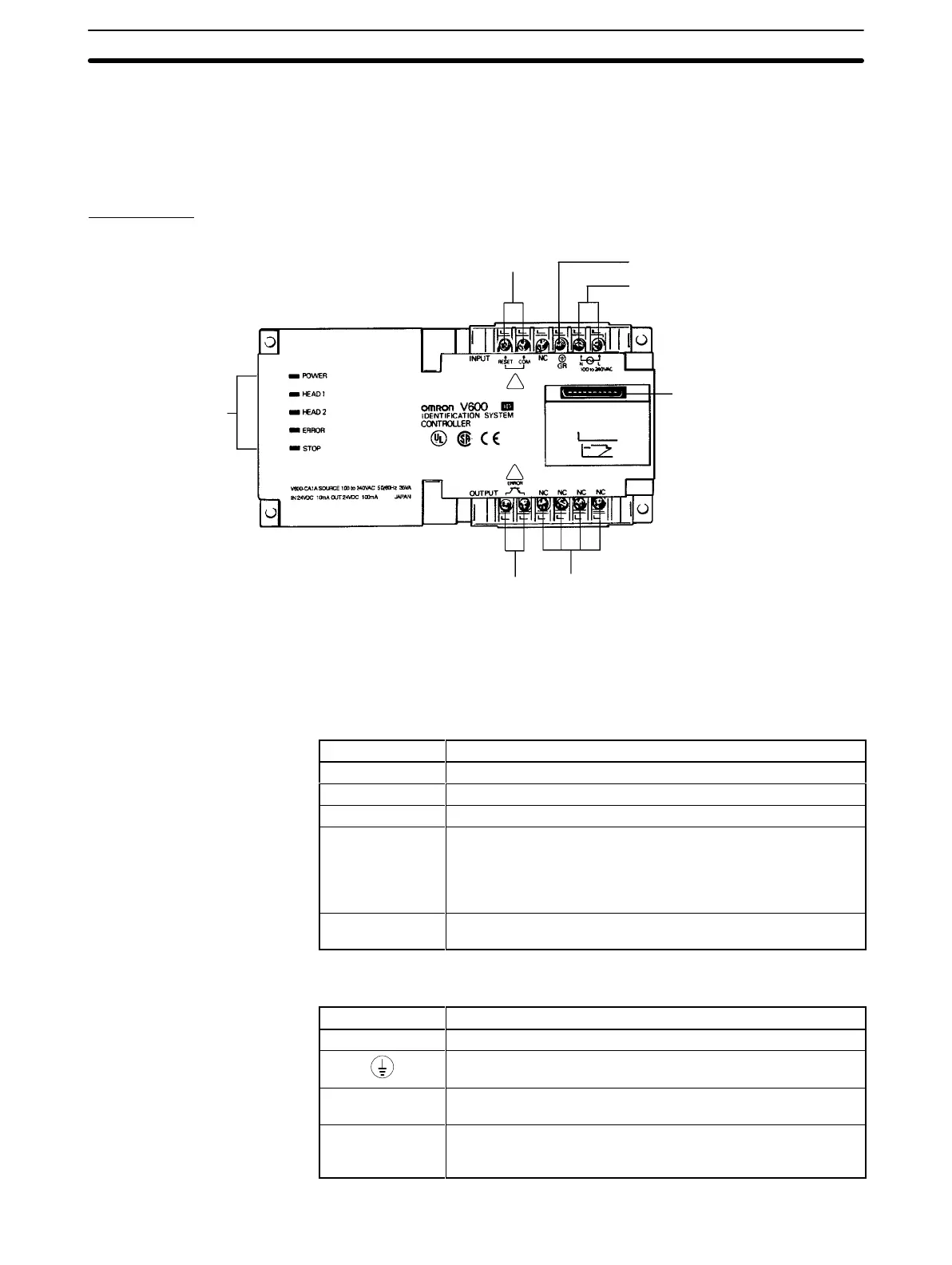
2-1-1 Nomenclature
Front Panel
Reset
input terminals
Protective conductor terminal
Power supply terminals
Open terminals (do not use)
Error output terminals
Operation indicators
V600-CAjA-Vj
ID Controller
Monitor Unit connector
!
!
Note Where there is no reference to the “V600-CA1A-Vj only” or the
“V600-CA2A-Vj
only” is given, all information in this section is common to both.
Operation Indicators
Name Description
POWER (green) Lit when power is applied.
HEAD 1 (green) Lit when R/W Head 1 is communicating.
HEAD 2 (green) Lit when R/W Head 2 is communicating.
ERROR (red) Lit when an ID Controller operation stop error (CPU error,
memory error) is detected, or when an error in communications
with an IBM PC/AT or compatible or with R/W Heads is
detected. Error messages can be read from the host computer
or Monitor Unit.
STOP (red) Lit when an operation stop error (CPU error, memory error)
occurs, or when an external reset input is received.
Terminal Connections
Name Description
100 to 240 VAC Connection for the 100 to 240 VAC (50/60 Hz) power supply.
GR
Protective conductor terminal. Connect a dedicated ground
cable here and ground at a resistance of less than 100 Ω.
RESET/COM Emergency stop external reset input. Use a 24-VDC power
supply.
ERROR External output terminal for error signals when an operation
stop error is detected. Connect via a 24-VDC relay or similar
device.

 Loading...


