154
SECTION 5
V680 Commands
RFID System
User’s Manual
SECTION 5
Communications
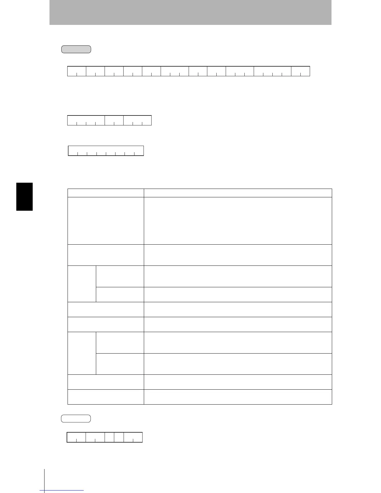
3. Set the Output Conditions
Note: There are the following three patterns for comparison conditions A and B depending on the con-
ditions.
• When Data Criteria Are Used for Conditions A and B
• When “ER” Is Specified as the Communications Criteria for Conditions A and B
• When “OK” or “AL” Is Specified as the Communications Judgements Conditions A and B
There are no parameters in this case.
Process code Always “00”.
Operation condition parameter “S1”: OUT1 output condition setting
“S2”: OUT2 output condition setting
“S3”: OUT3 output condition setting
“S4”: OUT4 output condition setting
Note: “S3” or “S4” will result in an error (15) in Two Output Mode. Also, if output conditions
are not set for OUT1 through OUT3, the execution command output destination cannot be
set.
Comparison antenna “01”: Compare to channel 1
“02”: Compare to channel 2
“XX”: No output
Conditions
A and B
Data criteria “==”: Criteria data match, “!=”: Criteria data does not match,
“>=”: Equal to or higher than criteria, “<=”: Equal to or less than criteria,
Data criteria can be used only for READ commands.
Communications cri-
teria
“OK”: Communication OK, “ER”: Communications error, “AL”: Always
Data offsets A and B Specifies the offset to the portion of the read data to use as the criteria.
Setting range: 0000
H to FFFFH
Number of data bytes A and B Specifies the number of bytes to use as the criteria.
Setting range: 01
H to 10H
Compari-
son param-
eters A and
B
When conditions A
and B are data crite-
ria
Specifies the comparison data to use as the data criteria.
(The same length as the designated number of data bytes for either ASCII and hexadeci-
mal data.)
When conditions A
and B are “ER” com-
munications criteria
Specifies the error code.
“00000000” specifies all error codes.
Example: “707A0000”specifies a Tag communications error and address error.
Operator Operator between condition A and condition B
“&&”: AND, “++”: OR
Output parameter Specifies the output ON time in milliseconds.
Setting range: “0001” to “9999” (ms), (“0000”: Hold until next judgment)
Command
SE
2
2
00
2
××
××
2
××
Operator
2
×
Comparison
parameter A
×
...
n
2
*
CR
××
Output parameter
4
××
×
Comparison
parameter B
×
...
n
××
Condition A
2
××
Condition B
2
Terminator
Command
code
Process
code
Operation
condition
parameter
Compari-
son
antenna
×××
2n
...
×
Comparison parameters
A and B
× ×
4
××
Comparison
parameters A and B
Number of data
bytes A and B
×××
8
×
Comparison parameters A and B
× ×××
Response
SE
2
2
*
CR
2
××
1
0
1
0
Command
code
Terminator End code
Resend
flag
Fixed
value

 Loading...


