RFID System
User’s Manual
SECTION 7
Specifications and Dimensions
SECTION 7
Appendices
253
I/O Specifications
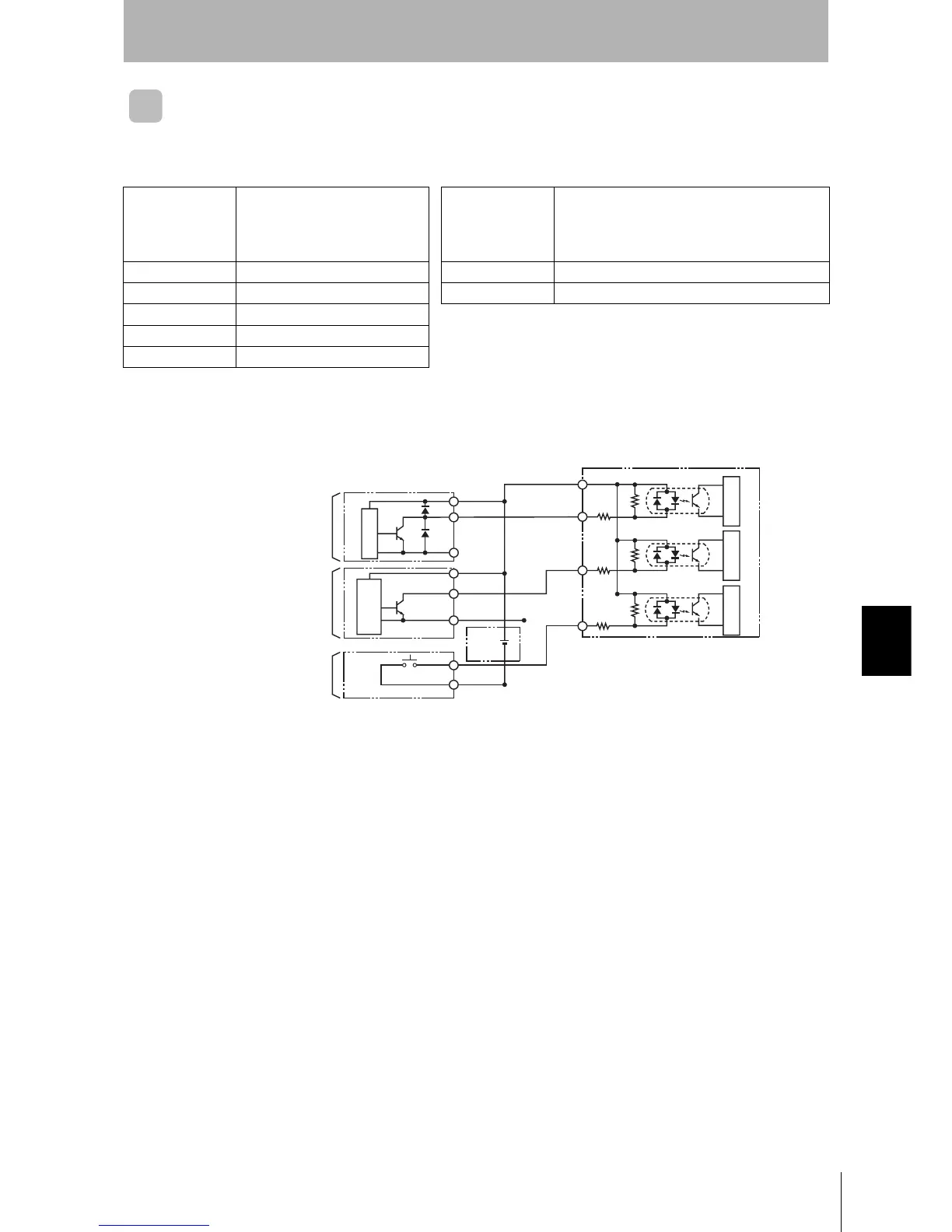
Example Wiring to Input Devices
Input Section
●Input Specifications (RST, TRG, TRG2) ●Output Specifications (RUN, BUSY/OUT3, ERROR/OUT4, OUT1,
OUT2)
Input voltage 24 VDC +10% (including ripple)
−15%
Maximum
switching capacity
24 VDC +10% (including ripple)
−15%
(either PNP or NPN) 100 mA, PhotoMOS relay output (either PNP or
NPN)
Input impedance 2.2 k
Ω Leakage current 100 µA max.
Input current 10 mA typical (24 VDC) Residual voltage 2.0 V max.
ON voltage 19 V min. Note 1. When the RST input turns ON, the CPU stops operation, the RST
indicator lights, and the ERROR output is reset.
2. The transistor may be damaged if the output is short-circuited
with no load.
OFF voltage 5 V max.
Input response time 70 ms max.
● PLC Output Unit
● NPN transistor output
open collector
(e.g., 3-wire Sensor)
● Contact output
(e.g., pushbutton switch)
(C200H-OD21,
C500-OD412, etc.)
24-VDC
power
supply +
+V
OUT
0 V (COM)
+V
0 V
Output
RST
TRG1
TRG2
ID Controller input section
COM_I
2.2 kΩ
2.2 kΩ
2.2 kΩ
Internal circuitInternal circuitInternal circuit
Internal circuit
Internal sensor
circuit