33
RFID System
User’s Manual
SECTION 2
Connection and Wiring
SECTION 2
Installation, Connections, and Wiring
Mounting Cables
Use the connectors provided with the ID Controller.
1. Attach the crimp terminals to the sections of the cable where the
sheath has been stripped.
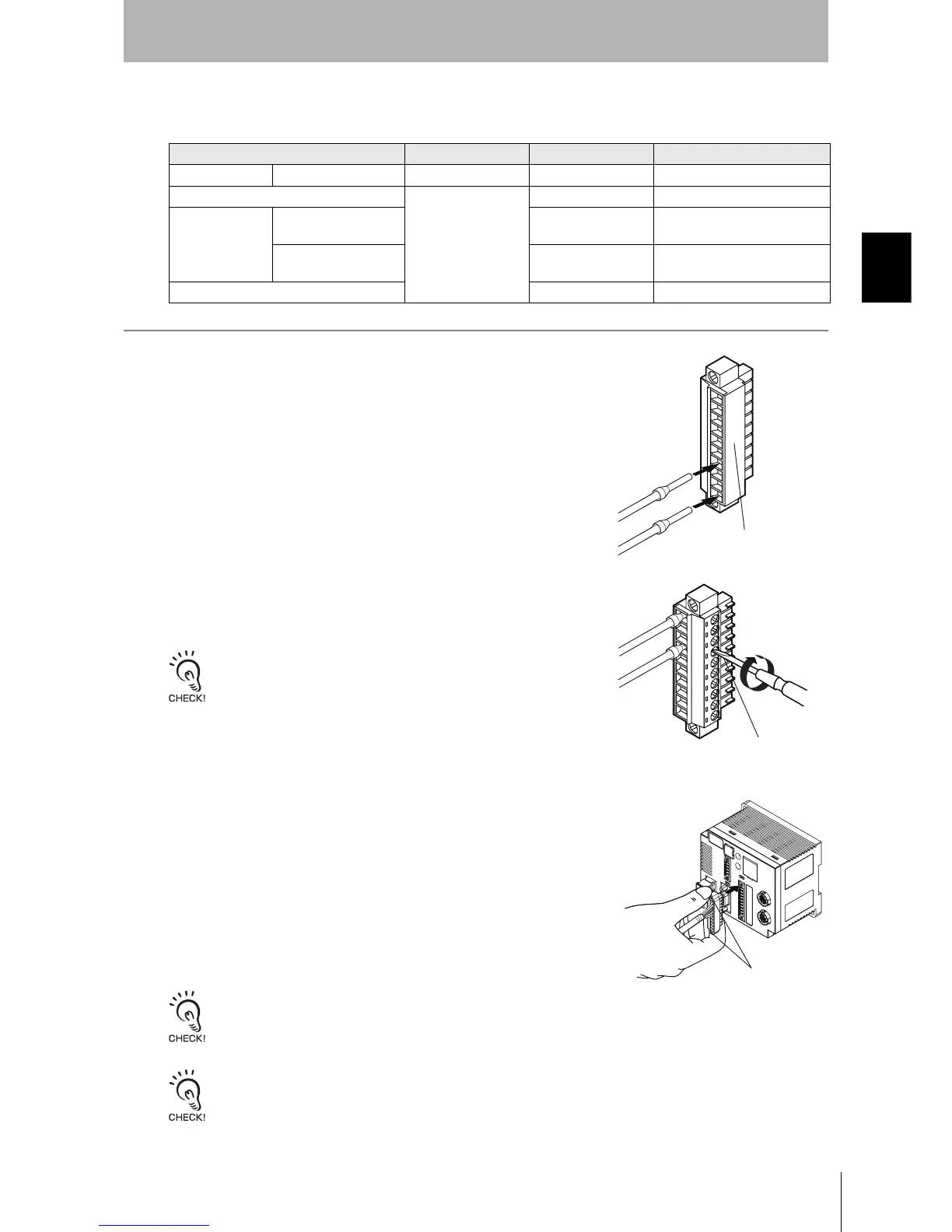
2. Make sure the connector is facing the right direction and insert each
crimp terminal into the correct connector hole.
3. Firmly tighten the connector cable screws.
Recommended tightening torque: 0.22 N·m
Use a small flat-blade screwdriver with a uniform thickness. Do not
use a standard screwdriver with a tapered end. A standard screw-
driver will not fully insert into the hole.
4. Once all of the cables have been connected to the connector,
attach the connector to the ID Controller.
Align the cable connector with the connector on the ID Controller. Hold the connector
body and push the connector firmly into place, and then tighten the connector lock
screws.
Recommended tightening torque: 0.4 N·m
Removing the Connector
Completely loosen the two lock screws, hold the protruding part of the connector, and pull straight out. If
the connector is difficult to remove, press on the ID Controller while pulling on the connector.
Do not connect cables to the connector after attaching the connector to the ID Controller.
Manufacturer Model Remarks
Cable I/O lines --- --- 0.5 mm
2
(equivalent to AWG 20)
Connector
Phoenix Contact
MC1.5/10-STF-3.5 ---
Crimp terminals When connecting 1 line
to each terminal
AI0.5-8WH
---
When connecting 2
lines to each terminal
AI-TWIN2
× 0.5-8WH
---
Crimping Tool CRIMPFOX UD6 ---
Connector: MC1.5/10-STF-3.5
(manufactured by Phoenix Contact)
Small flat-blade screwdriver
with a tip of uniform thickness.
Lock screws