32
SECTION 2
Connection and Wiring
RFID System
User’s Manual
SECTION 2
Installation, Connections, and Wiring
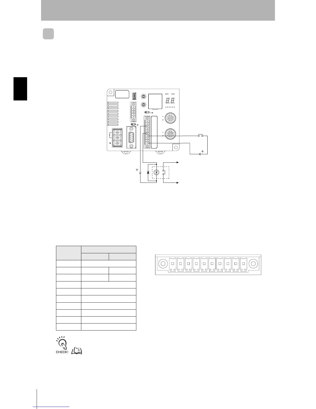
Wiring I/O Lines
Precautions for Reset Signal Input
• Be sure that the input voltage does not exceed the maximum applicable voltage (26.4 V).
The device may malfunction if the rated voltage is exceeded.
• To improve noise resistance, install the input line 1 m or more away from high-voltage devices and
power lines.
Precautions for Error Signal Output
• The maximum switching capacity for the output is 100 mA at 24 VDC (−15% to +10%).
Do not use voltages or loads that exceed the switching capacity. Doing so may cause malfunctions.
• Use an auxiliary relay (24 VDC, 100 mA max.) to connect the output circuit.
Pin Arrangement
Refer to External I/O Port for details on the external I/O port.
p. 14
Pin No.
Name
V600 I/O V680 I/O
1RUN
2 BUSY OUT3
3 ERROR OUT4
4OUT1
5OUT2
6COM_O
7RST
8TRG1
9TRG2
10 COM_I
Reset input
24 VDC
24 VDC
To error output
Terminal No.
12345678 910
• Controller Terminal Arrangement