34
SECTION 2
Connection and Wiring
RFID System
User’s Manual
SECTION 2
Installation, Connections, and Wiring
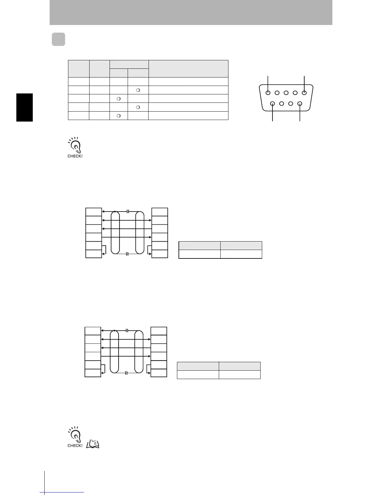
RS-232C Port
Pin Arrangement
The pin arrangement is different from that of the V680-CA1A. Use an RS-232C cable for the V680-CA5D@@-
V2.
Connections to Host Device
Example Connection to OMRON PLC
Recommended Cable
Example Connection to IBM PC/AT or Compatible Computer via D-SUB 9-pin Con-
nector
Recommended Cable
Refer to Connections between ID Controllers (1:N) for information on 1:N connections.
p. 39
Model Manufacturer
XW2Z-@@@TOMRON
Note 1. Ground the shield at the host device side to prevent operation errors.
2. Short-circuit pins 4 (RS) and 5 (CS) inside the connector.
Model Manufacturer
XW2Z-@@@S-V OMRON
Note 1. The interface cable will have a male connector on the ID Controller and a female connector on the IBM PC/AT or com-
patible.
2. Ground the shield at the host device to prevent operation errors.
Pin No. Symbol
Signal direction
Signal name
Input Output
9 SG --- --- Signal ground or common return line
2 SD --- Send data
3 RD --- Receive data
4 RS --- Request to send
5 CS --- Clear to send
51
96
• Controller Terminal Arrangement
ID Controller
Host device
(Shield)
GR
SG
SD
RD
RS
CS
GR
SG
RD
SD
RS
CS
ID Controller
IBM PC/AT or compatible
(
Shield)
GR
SG
SD
RD
RS
CS
GR
SG
RD
SD
RS
CS