39
RFID System
User’s Manual
SECTION 2
Connection and Wiring
SECTION 2
Installation, Connections, and Wiring
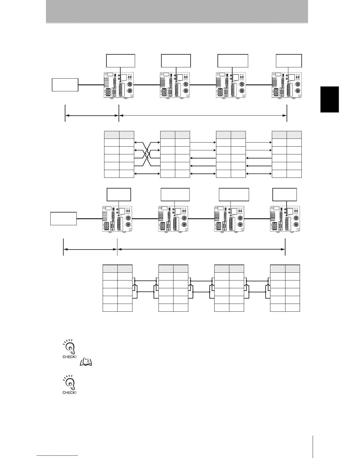
Connections between ID Controllers (1:N)
RS-232C Connection to the Host Device
Note: Short-circuit terminals 1 and 3, and 2 and 4 to use RS-485 communication.
Refer to Connections to Host Device for information on RS-232C connections between the host device and ID Control-
lers.
p. 34
If the first communications received by an ID Controller are via the RS-232C interface, reception of RS-422/RS-485
communications will be prohibited. If the first communications are received via RS-422/RS-485, reception of RS-232C
communications will be prohibited. Therefore, when changing the system configuration of an ID Controller, always turn
OFF the power supply before changing the connections.
ID ControllerID Controller
RS-422
ID Controller
RS-422
ID Controller
RS-422
Pin No. Symbol
1RDA(−)
2 RDB(+)
3SDA(−)
4 SDB(+)
5SG
SW 6: OFF
(no terminating
resistance)
Pin No. Symbol
1RDA(−)
2 RDB(+)
3SDA(−)
4 SDB(+)
5SG
Pin No. Symbol
1RDA(−)
2 RDB(+)
3SDA(−)
4 SDB(+)
5SG
Pin No. Symbol
1RDA(−)
2 RDB(+)
3SDA(−)
4 SDB(+)
5SG
Host device
RS-232C
SW 6: ON
(terminating
resistance)
Max. length: 15 m Total length: 500 m max.
SW 6: OFF
(no terminating
resistance)
SW 6: ON
(terminating
resistance)
RS-485 RS-485RS-485
1RDA(−)
2 RDB(+)
3SDA(−)
4 SDB(+)
5SG
1RDA(−)
2 RDB(+)
3SDA(−)
4 SDB(+)
5SG
1RDA(−)
2 RDB(+)
3SDA(−)
4 SDB(+)
5SG
1RDA(−)
2 RDB(+)
3SDA(−)
4 SDB(+)
5SG
RS-232C
ID Controller
Pin No. Symbol
SW 6: OFF
(no terminating
resistance)
Host device
SW 6: ON
(terminating
resistance)
Max. length: 15 m
Total length: 500 m max.
SW 6: OFF
(no terminating
resistance)
SW 6: ON
(terminating
resistance)
ID Controller
ID Controller
ID Controller
Pin No. Symbol Pin No. Symbol
Pin No.
Symbol