38
SECTION 2
Connection and Wiring
RFID System
User’s Manual
SECTION 2
Installation, Connections, and Wiring
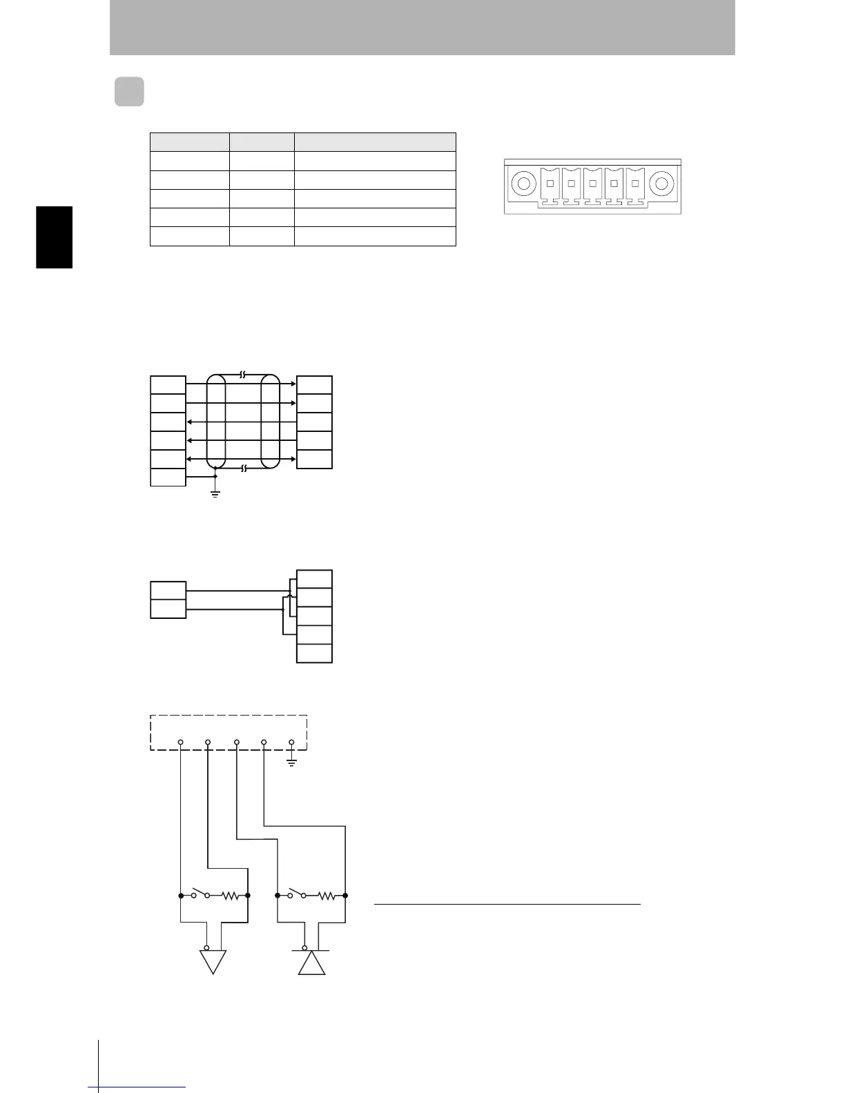
RS-422/RS-485 Port
Pin Arrangement
Connections to Host Device
RS-422 Connections
RS-485 Connections
Pin No. Name Details
1RDA(
−) Receive data
2 RDB(+) Receive data
3SDA(
−) Send data
4 SDB(+) Send data
5SGSG
Note: The port can be used as an RS-485 port if terminals 1 and
3, and 2 and 4 are short-circuited.
Note: Ground the shield at the host device to prevent operation errors.
Note: Short-circuit terminals 1 and 3, and 2 and 4. Do not connect anything to the ID Controller signal ground.
Terminal No.
12345
• Controller Terminal Arrangement
ID Controller
Host device
(
Shield)
RDA(−)
RDB(
+)
SDA(
−)
SDB(
+)
SG
SDA(
−)
SDB(
+)
RDA(
−)
RDB(
+)
SG
GR
ID Controller
Host device
RDA(
−)
RDB(
+)
SDA(−)
SDB(
+)
SG
−
+
Reception
terminating
resistance
Transmission
terminating
resistance
RDA(−) RDB(+)SDA(−) SDB(+)SG
Terminating resistance: 220 (Ω) for RS-422, 110 (Ω) for RS-485
Note: Turn ON terminating resistance only at the ID Controllers at the both ends
of the trunk cable. Turn OFF the terminating resistance at all ID Controllers
in between. Normal transmissions will not be possible if terminating
resistance is turned ON for the ID Controllers in between.